|
Quality Management and Safety Engineering (BSc) - MST 326 Project planning. |
PowerPoint presentation: 764 KB
"A golden rule in terms of estimating the time required is to assume people are only productive four out of five days" [1].
A Gantt chart is a graphical representation of the duration of tasks plotted against time. The Smartdraw.com web pages (links below) indicate the wide variety of ways in which Gantt charts can be implemented.
The Program Evaluation Review Technique (PERT) chart is a graphic representation of the schedule for a project developed by the US Navy for the Polaris missile programme. It shows the sequence of tasks, indicates which tasks can be performed simultaneously, and permits determination of the critical path for the individual tasks to be completed on time in order for the project to meet its completion deadline. The chart may show a variety of parameters, including earliest and latest start dates for each task, earliest and latest finish dates for each task, and slack time between tasks. A PERT chart can be used to document an entire project or a key phase of a project. The chart allows a team to avoid unrealistic timetables and schedule expectations, to help identify and shorten tasks that are bottlenecks, and to focus attention on most critical tasks.
The Critical Path Method (CPM), developed by the private sector for project management around the time that PERT was started, has become synonymous with PERT, and may be referred to as any of a variety of names: CPM, PERT or PERT/CPM. The critical path is the set of tasks (each dependent on the preceding one) which together take the longest time to complete. The PERT/CPM chart may be preferred over the Gantt chart as it clearly illustrates task dependencies, although it can be much more difficult to interpret.
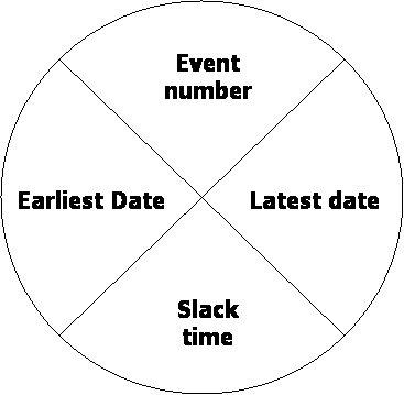
PERT/CPM can be drawn in a number of ways, but often consists of a series of nodes as in the Figure below, connected by arrows which indicate the duration of the operation leading to the event (i.e. the completion of an operation).

By filling in the respective quadrants working from left-to-right and also from right-to-left it is possible to identify the limiting stages of the process and where slack-time occurs. This in turn could be used to identify workers with unproductive time which might be redeployed within the operation or where the bottlenecks occur in the process to permit these to be tackled for the overall benefit of the system.
The actual timings may not be accurately known. It is normal to estimate:
These times can then be used to specify a beta distribution with a mean value X and a variance S2 using the following equations [2]:
Having all tasks specified as density functions, permits the production of a density function for the overall project completion time.
Reference
URLs for project management (checked as live on 28 February 2005):