Young's moduli, Poisson's ratios, shear and bulk moduli
PowerPoint
papers
Index

| Composites Design and Manufacture (Plymouth University teaching support materials) Young's moduli, Poisson's ratios, shear and bulk moduli |
Lecture PowerPoint |
Review papers |
Subject Index |
|
Go direct to:
| E | Young's modulus |
Hooke's Law [1] originally stated that a change in length was proportional to the load, but now it has been generalised to denote that the stress (σ) is proportional to the strain (ε) with the constant of proportionality known as Young's modulus (E), so that σ = Eε. Traditional structural engineering materials are isotropic and hence the value of E is independent of direction. However, the Young's modulus of a composite material is anisotropic (varies with direction) and can be estimated using the rule-of-mixtures [2]:
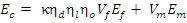 |
Equation 1 |
where:
Ec = Young's modulus of the composite
Ef = Young's modulus of the fibre
Em = Young's modulus of the matrix
Vf = fibre volume fraction
Vm = matrix volume fraction (1-Vf-Vv)
Vv = void volume fraction
κ = fibre area correction factor (set at unity for circular cross-section fibres)
ηd = fibre diameter distribution factor (set at unity for man-made fibres)
ηl = fibre length distribution factor
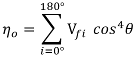
ηo = fibre orientation distribution factor
For a unidirectional continuous fibre composite aligned with the stress, the physical assumption underlying the equation above is compatibility of strain between the fibre and the matrix resulting in the constituent phases carrying load in proportion to their respective volume fractions and moduli. Further, the above equation has a number of underlying assumptions [3-6]:
The rule of mixtures can be used for other "elastic" properties (e.g. density, Poisson's ratio, coefficient of thermal expansion and hygrothermal properties).
The fibre length distribution factor (FLDF) assumes that:
Figure 1: Diagrammatic representation of the stress distribution in a short fibre,
with shear stress at the fibre matrix interface shown in red, tensile stress in black and
peak stress (Efε) shown in green.
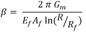
FLDF can be calculated using the Cox equation [8]:
 |
Equation 2 | [8] |
where:
 |
Equation 3 | [8] | |
| and: | |||
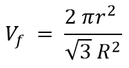 |
Equation 4 | [9] |
and where Gm is the shear modulus of the matrix, L is the fibre length, Af is the cross sectional area of the fibre, Rf is the radius of the fibre and R is the mean separation of the fibres. If the fibre is shorter than the critical length (lc), it will never carry a load high enough to cause fibre fracture. The composite will instead fail in shear, either at the fibre/matrix interface or in the matrix itself. Alternative Equations for the prediction of β have been proposed by Nayfeh [10] and McCartney [11]. Nairn [12] has extended the shear-lag analysis from concentric cylinders to a generalized form (with an new βcor as Equation 44 in his paper) with transverse variations of shear stress described by arbitrary shape functions. The new analysis permits modelling of imperfect interfaces both between concentric cylinders [13] and within multilayered structures [14]. Modification of the prior shape functions permits extended shear-lag analysis to work for any fibre volume fraction (previous models were unacceptable at low fibre volume fraction). The full shear-lag analysis can model stress transfer for both isotropic and anisotropic fibres.
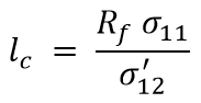
The critical length (when there is no debonding) is given by the expression:
 |
Equation 5 | [8] |
where R is the fibre radius, σ11 is the tensile stress in the fibre and σ'12 is the shear strength (of the interface or of the matrix as appropriate).
and the fibre orientation distribution factor can be calculated using the Krenchel equation [15]:
 |
Equation 6 | [15] |
For a unidirectional ply, the rule-of-mixtures does assume that:
and typical values used in the equation would be:
Ef = 70 GPa (glass), 140 GPa (aramid) or 210 GPa (carbon)
Em = 1-3 GPa (polymers) or 70 GPa (aluminium)
Vf = 0.1-0.3 (random), 0.3-0.6 (woven) or 0.5-0.8 (unidirectional)
ηl = 0 (if significantly less than the critical length) varying up to 1 (continuous fibres)
- ηo = 0.0 for unidirectional perpendicular to the fibres
- ηo = 1/4 for biaxial on the bias angle (at ±45º to the fibres)
- ηo = 3/8 for random in-plane
- ηo = 1/2 for biaxial parallel to the fibres
- ηo = 1.0 for unidirectional parallel to the fibres
For a continuous fibre carbon/resin composite (Ef = 210 GPa, Em = 3 GPa with Vf = 70% for unidirectional or Vf = 50% for bidirectional), Figure 2 illustrates how the Young's modulus calculated from the rule-of-mixtures varies with change in the angle between the applied stress and the fibre direction:
Figure 2: Variation of Young's modulus with fibre orientation
The materials data above is representative and should not be used for 'design' purposes.
The Halpin-Tsai method [16] is a semi-empirical set of widely used micromechanical equations used to predict/estimate the macroscopic material stiffness (elastic moduli). Whereas the rules-of-mixture use fibre length/orientation distribution factors, Halpin-Tsai has a curve-fitting parameter, ζ (zeta) or occasionally ξ (xi), that depends on the inclusion geometry, packing/spatial arrangement, and loading direction of the filler or fibre. Shokrieh and Moshrefzadeh-Sani [17] have questioned the coefficient which is assumed to be constant in the traditional Halpin-Tsai equation for the elastic modulus of randomly oriented composites. Their research suggests that the coefficient depends on the matrix and reinforcement properties. By combining the Mori-Tanaka (MT) mean field homogenisation [18] and Laminated Analogy (LA) [19] methods, the new Mori-Tanaka and Laminated Analogy (MT-LA) model can estimate the properties of randomly oriented (nano-)composites.
The Voigt (1887) [20] constant strain and Reuss (1929) [21] constant stress models for load sharing in materials can be applied to composites. One source [ NB: I cannot currently trace where I found the transition point at 0.5% strain :-( ] states that:
The Reuss model suggests that up to 0.5% strain, there is equal stress in both the fibres and the matrix. The Reuss model for equal stress in the context of transverse stiffness is described in Hull and Clyne [22 page 63].
The Voigt model suggests that above 0.5% strain, there are equal increases in strain in both the fibres and the matrix.
| ν | Poisson's ratio |
Poisson's ratio is denoted by the Greek letter nu: ν. It has a value determined by:
ν = -(strain normal to the applied stress)/(strain parallel to the applied stress)
Tensile deformation is taken as positive and compressive deformation is taken as negative. The minus sign in the definition of Poisson's ratio normally results in positive values of Poisson's ratio and a thermodynamic constraint which restricts the values to -1 < ν < 1/2.
For an orthotropic composite, there may be a different Poisson's ratio associated with each plane. Maxwell’s reciprocal theorem [23] states that two strains must be equal if the two stresses are of equal magnitude and sense. It is implicit in the symmetry of the stiffness/compliance matrices for a square symmetric material (E2 = E3) that:
ν12E2 = ν21E1,Lemprière [24] generalised the above thermodynamic constraint for the case of orthotropic materials where both the stiffness and compliance matrices are positive-definite (i.e. E1, E2, E3, G23, G13, G12 > 0) to yield the following results:
and hence ν12 = ν13, ν21 = ν31 and ν23 = ν32.
(1-ν23ν32), (1-ν13ν31), (1-ν12ν21), (1-ν12ν21-ν13ν31-ν23ν32-2ν21ν32ν13) > 0
and thus
νij ≤ (Ei/Ej)1/2 and ν21ν23ν13 < 1/2.
Craig and Summerscales [25] measured the Poisson's ratios in all three planes for two glass-fibre laminates
C1: 13 layers of Fothergill and Harvey Y119 unidirectional rovings with 25% fibre volume fraction
(based on fabric areal weight = 640 gsm, fibre relative density = 2.56, panel thickness = 11 mm) [26]
A2: 12 layers of TBA 830 gsm ECK25 woven rovings in Crystic 625TV resin
(based on fabric areal weight = 830 gsm [27, 28], fibre relative density = 2.56, panel thickness unknown)
and confirmed that the Lemprière criteria were valid for both materials (Table 1):
| Unidirectional | Unidirectional | Woven | Woven | |
| Panel C1: ν, E or G | Panel C1 √Ei/Ej | Panel A2: ν, E or G | Panel A2 √Ei/Ej | |
| ν12 | 0.308 | 1.606 | 0.140 | 0.942 |
| ν21 | 0.123 | 0.623 | 0.109 | 1.061 |
| ν13 | 0.354 | 1.687 | 0.408 | 1.285 |
| ν31 | 0.124 | 0.593 | 0.247 | 0.778 |
| ν23 | 0.417 | 1.051 | 0.380 | 1.364 |
| ν32 | 0.414 | 0.952 | 0.297 | 0.733 |
| E1 (GPa) | 20.3 | 15.5 | ||
| E2 (GPa) | 7.9 | 17.5 | ||
| E3 (GPa) | 7.1 | 9.4 | ||
| G12 (GPa) | 3.45 | 3.0 |
If one Poisson's ratio in an orthotropic material is negative, then no restriction is placed on the other two values. Dickerson and Di Martino [29] published data for cross-plied boron/epoxy composites in which the Poisson's ratios range from 0.024 to 0.878 in the orthotropic case and from -0.414 to 1.97 for a ±25º laminate.
Materials and structures with negative Poisson's ratios do exist and are termed auxetic. The state-ot-the-art of auxetics research in the UK was reviewed by KTN in 2016 [30]. A variety of often re-entrant or chiral structures (Figure 3) achieve this effect, as in the animation below from Rod Lakes (University of Wisconsin) webpage on Negative Poisson's ratio materials:
 ............
Figure 3: Re-entrant (left) and chiral (right) auxetic (negative Poisson's ratio) structures (from Rod Lakes webpage)
Cork oak bark at high compressive strains has a negative Poisson's ratio under non-radial stresses, but has a positive Poisson's ratio when compressed in the radial direction [31].
| G | Shear modulus |
The inter-relationship of the elastic constants for isotropic materials is given by:
| G = E/2(1+ν) | Equation 7 | [1] | |
| K= E/3(1-2ν) | Equation 8 | [1] |
where E is the Young’s modulus, G is the shear modulus, K is the bulk modulus and ν is Poisson’s ratio.
For orthotropic materials within a single plane, Huber [28] proposed that the shear modulus would be predicted by:
 |
Equation 9 | [32, 33] |
although his original work was for reinforced concrete slabs. Panc [33] used theoretical considerations to show that the expression may be used as an approximation. Cheng and He [34] and Bert et al [35] have considered the use of this Equation in the context of fibre-reinforced composites and conclude that although the relation is inaccurate, and can lead to large errors in the shear modulus G, the use of the relation in the governing differential equations does still yield very accurate final solutions.
Craig and Summerscales [25] used Huber’s equation to validate the elastic constants measured in the plane of the reinforcement for both unidirectional and woven fibreglass panels and presented data for the Poisson's ratios in all three orthogonal planes (Table 1). For an orthotropic composite, the shear modulus in any plane will change as the fibre axes are rotated relative to the applied biaxial stress. The optimum correlation of theory and experiment was obtained when Huber's equation was used to obtain the shear modulus G12(45°) rather than GLT measured when the sample is rotated by 45°.
Table 2 presents the mechanical property data used for a unidirectional (UD) CFRP customised Finn dinghy rudder with fibres on axis 1 [36].
Table 3 presents compiled similar data for a woven (WR) CFRP with fibres on axes 1 and 2 [37].
| Composite | Axes subscripts |
Elastic modulus Ex (GPa) |
Shear modulus Gxy(GPa) |
Poisson's ratio | Tensile strength Fxt (MPa) |
Compressive strength Fxc (MPa) |
Shear strength F13 (MPa) |
|---|---|---|---|---|---|---|---|
| UD CFRP [36] | 11 12 |
135 | 4.7 | 0.27 | 2550 | 1470 | 60 |
| UD CFRP [36] | 22=33 13=23 |
8.6 | 3.1 | 0.4 | 69 | 100 | 32 |
| WR CFRP [37] | 11=22 12=13 |
69.4 [38] | 5.0 [38] | 0.08 [38] | 907 [38] | 54.3 [40] | |
| WR CFRP [37] | 33 23 |
11.5 [38] | 3.4 [39] | 0.53 [38] | 63 [40] |
Khashaba [41] used a modified Iosipescu test fixture to investigate the in-plane shear properties of cross-plied E-glass/epoxy composite laminates with different off-axis angles. The maximum in-plane shear modulus (plus maximum Poisson's ratio and minimum Young's modulus) was found for specimens with [+45°/−45°]2s stacking sequence . The minimum in-plane shear strength was found in specimens with [0°/90°]2s and [90°/0°]2s stacking sequences. The experimental results agreed very well with the predicted in-plane shear moduli in Table 2. Orthotropic shear moduli for carbon fibre composites are given in Table 3.
| Off-axis angle | Stacking sequence | Exx=Eyy (GPa) | νxy (GPa) | Gxy (GPa) |
| LY138-1/HY 5138 epoxy resin | N/A | 3.2 | 0.36 | 1.18 |
| 17 μm 1.15 g/m E-glass roving | N/A | 72.4 | 0.22 | 30.13 |
| 0° | [0°/90°]2s | 21.0 | 0.129 | 2.71 |
| 15° | [+15°/-75°]2s | 15.6 | 0.352 | 3.29 |
| 30° | [+30°/-60°]2s | 10.3 | 0.571 | 5.79 |
| 45° | [+45°/-45°]2s | 8.85 | 0.633 | 9.30 |
| 60° | [+60°/-30°]2s | 10.3 | 0.571 | 5.79 |
| 75° | [+75°/-15°]2s | 15.6 | 0.352 | 3.29 |
| 90° | [90°/0°]2s | 21.0 | 0.129 | 2.71 |
| Laminate | G12 (GPa) | G13 (GPa) | G23 (GPa) |
| unidirectional | 4.6 ± 0.2 | 5.2 ± 0.3 | 3.0 ± 0.4 |
| [0°4/90°4]2s | 4.7 ± 0.14 | 4.5 ± 0.3 | 4.3 ± 0.05 |
| [±45°/90°/0°]4s | 17.9 ± 0.3 | 3.9 ± 0.2 | 3.9 + 0.2 |
| K | Bulk modulus |
By extension of Equation 8, Summerscales [43] proposed that the bulk modulus for a square symmetric material could be predicted from the following equation:
 |
Equation 10 | [43] |
This equation reduces to the isotropic form when E1 = E2 = E3 and ν12 = ν21 = ν23.
Table 4 gives values for Young’s moduli E, Poisson’s ratios ν and bulk moduli Kref (all moduli in GPa) for various materials. The abbreviation (iso) is used to indicate isotropic properties. The unidirectional carbon fibre composites in the Table are square symmetric. Equations 9 and 10 have been used to predict the bulk moduli Kcalc for the isotropic and square symmetric materials respectively.
| Material | E1 | E2 | E3 | ν12 | ν21 | ν23 | Kref | Kcalc | Ref. |
| Epoxy resin | 2.4 | (iso) | (iso) | 0.34 | (iso) | (iso) | - | 2.5 | [45] |
| Crown glass | 71.3 | (iso) | (iso) | 0.22 | (iso) | (iso) | 41.2 | 42.4 | [46] |
| Heavy flint glass | 80.1 | (iso) | (iso) | 0.27 | (iso) | (iso) | 57.6 | 58.0 | [46] |
| Graphite | - | - | - | - | - | - | 33.0 | - | |
| Carbon fibre/epoxy composites | |||||||||
| High-modulus (HM) parallel | 287 | 7.75 | 7.75 | 0.3 | 0.01 | 0.55 | - | 11.3 | [47] |
| High-strength (HS) perpendicular | 177 | 11.7 | 11.7 | 0.33 | 0.02 | 0.47 | - | 13.6 | [47] |
| High-strength (HS) parallel | 172 | 11.6 | 11.6 | 0.36 | 0.024 | 0.48 | - | 14.0 | [47] |
| Carbon fibres | |||||||||
| Tenax HTA5131 carbon fibre | 238 | 28 | 28 | - | - | - | - | - | [48] |
Using the mercury porosimetry technique, Matthews and Ridgway [49] have estimated the bulk modulus of woven Tenax HTA carbon fibre Injectex and twill fabrics (Brochier SA, Dagneux - France) at 20 GPa and 7 GPa respectively. Both the Injectex and twill fabrics have the same fabric areal weight (290 gm-2) and are woven with fibres from the same batch.
Using the rule-of-mixtures, the unidirectional HS fibre composites might be assumed from the axial modulus to be ~70-75% fibre by volume of 238 GPa fibre. This would suggest a contribution of ~0.75 GPa from the resin to the bulk modulus, leaving a fibre bulk modulus of ~13 GPa (average of parallel and perpendicular composite moduli minus resin contribution). Note that this value lies between those estimated by Matthews and Ridgway.
The discrepancy between the predicted and measured bulk moduli for the carbon fibres may be due to any or all of the following assumptions:
The proposed equation for the prediction of the bulk modulus of anisotropic fibres gives values which are of the same order of magnitude as estimates from experimentally determined values.
Anisotropic elasticity theory
For information on implementing the above in tensor/matrix form, see the anisotropic elasticity theory page.
Additional teaching support material:
Stephen Grove: Rules of mixture for elastic properties
(University of Plymouth)
Polymer
Composites: layer property prediction (AEA Technology Materials Solutions)
References
Further reading