Hybrid composites.
PowerPoint
papers
Index

| Composites Design and Manufacture (Plymouth University teaching support materials) Hybrid composites. |
Lecture PowerPoint |
Review papers |
Subject Index |
|
Contents:
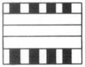
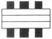
Forms of hybrid composite
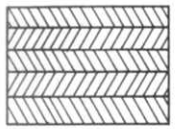
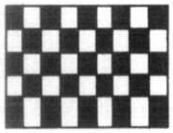
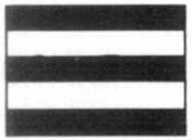
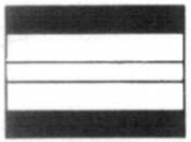
The incorporation of two or more fibres within a single matrix is known as "hybridisation" and the resulting material is a hybrid composite, often abbreviated to just "hybrid". Hybrid composites have been reviewed by several authors [1-5] and a classification scheme for hybrid composites was proposed by Short and Summerscales [2] which divided hybrid composites into 6 groups:
 |
 |
 |
 |
 |
 |
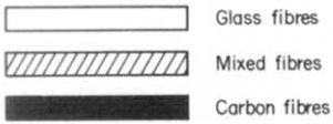 |
| A | B | C | D | E | F | KEY |
|
| |||||
Equations to predict hybrid strength
The Young's modulus of a hybrid composite can be predicted using a separate term for each fibre type:
where subscript A denotes the low elongation fibre and subscript B denotes the high elongation fibre. For a unidirectional composite, and assuming that the critical situation is fibre fracture and that the contribution from the resin matrix is negligible, a lower bound strength can be predicted using the higher value from either:
or

However, the above assumes that only one dominant fibre is carrying the load. The low elongation fibre can be assumed to be the critical failure case and if the high elongation fibre is also carrying load at the same strain, then:
The graphical method for the strength at constant strain is described below and in reference [8].
Summerscales and Short [9] presented an alternative model which assumed that the failure strain of the low elongation fibre could be increased to that of the high elongation fibre by isolating the individual critical fibre failures such that broken fibres were uniformly distributed through the composite. For fibres with closely matched strains to failure, where the high-modulus fibre has the low strain to failure and vice versa:
which predicts a strength that exceeds the rule of mixtures. This synergistic strengthening is known as the hybrid effect (but is as elusive as the Elixir of Life). The above equation was used to model data from Gruber [10] for Kevlar 49/E-glass hybrids, albeit giving an under-estimation of the values reported.
Constant Strain Graphical Method (CSGM) for hybrid strength
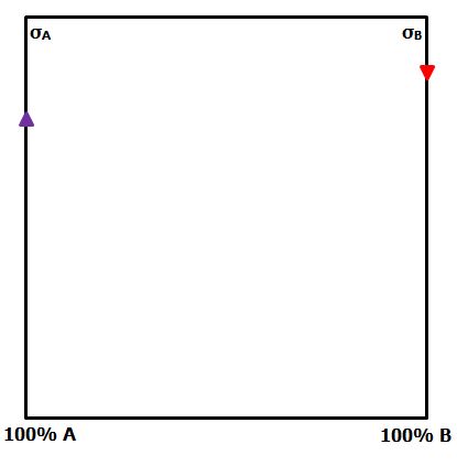 Assume the contribution of the matrix is negligible. Calculate the strength of each monofibre composite. Start a graph with Composite A on the left axis and Composite B on the right axis. Plot the respective strengths of each monofibre composite on the graph. |
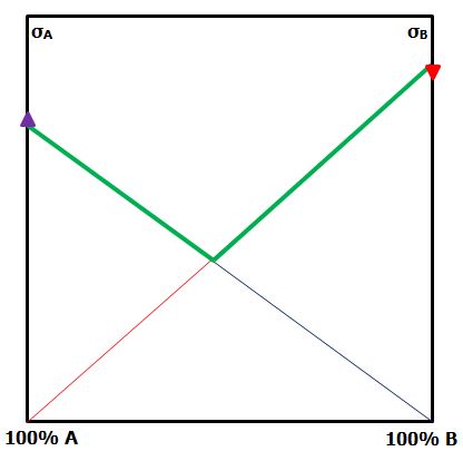 In the hybrid composite, as the proportion of either monofibre composite in the hybrid is reduced, the contribution it makes to the strength is reduced. Join each monofibre strength to the opposite origin. The green line represents the lower bound of hybrid strength. | 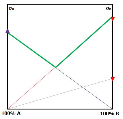 Figure 1: CSGM for hybrid strength If A is the low strain-to-failure fibre, assume it carries no load when B fails. However, when A fails, B is below its strain-to-failure and will carry load. Assume ε'B = 3 ε'A. Plot the stress in fibre B at the failure strain of fibre A on the right-hand axis. The area under the new line is the contribution of fibre B to the hybrid composite. | 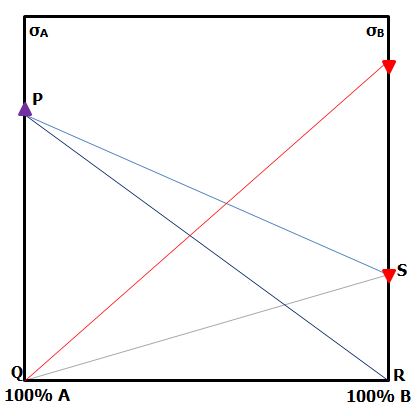 By similar triangles, join the strength of monofibre A to the stress in monofibre B The triangles PRS and QRS both have the same height at any proportion of the hybrid composite. | 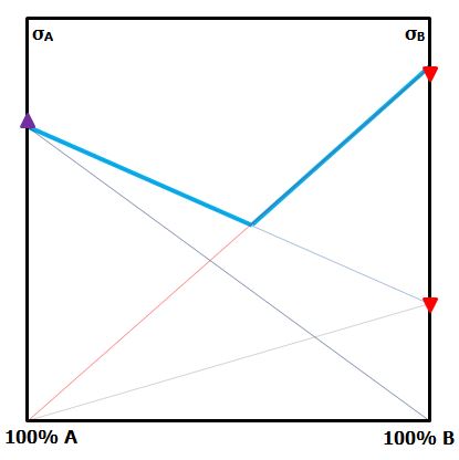 The middle bound hybrid strength is the blue line. |
Enhanced tensile stress at failure due to thermal strains
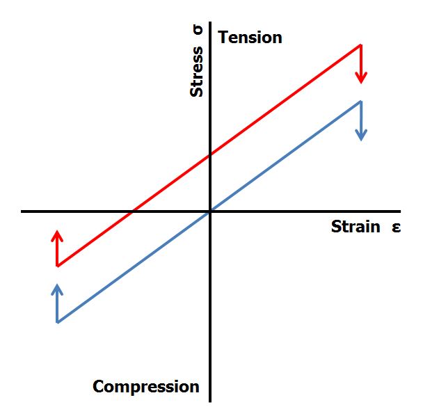
Consider the case of a unidirectional carbon fibre with glass fibre hybrid composite. Glass fibre has a normal coefficient of thermal expansion while carbon fibre has a zero or negative coefficient of thermal expansion. If the fibre to matrix bond is made at the peak cure temperature, then the system is locked together. When the composite cools to ambient temperature, the glass will shrink while the carbon fibre will not move or will grow. However, because the system is constrained by the cured matrix, the changes in dimensions will reach a balanced state. The carbon fibre will have residual compressive strain, while the glass fibre will have residual tensile strain. In Figure 2, the blue line represents the carbon fibre without residual strains, while the red line represents the carbon fibre in the hybrid composite. Clearly, the stress at failure is enhanced in tension, but reduced in compression.
The coefficient of thermal expansion (CTE) for a hybrid composite can be estimated by extension of the Schapery Equation [11]:
αc = ( Vfa αfa Efa + Vfb αfb Efb + Vm αm Em ) / Ec
where α is the CTE, Vx is the component volume fraction and Ex is the component elastic modulus with subscript x being c for composites, f for fibre and m for matrix with a and b representing the different fibres.
References