Filament winding. Pultrusion.
PowerPoint
papers
Index

| Composites Design and Manufacture (Plymouth University teaching support materials) Filament winding. Pultrusion. |
Lecture PowerPoint |
Review papers |
Subject Index |
|
Filament winding [1-9 and Ăström pp 241-251].
Filament winding is a process in which continuous fibre reinforcements are precisely positioned in a pre-determined pattern on a rotating mandrel (the mould tool for filament winding). Filament winding machines are normally computer numerically controlled (CNC) to permit highly automated production of axisymmetric components. A simple machine may have just two motions (degree-of-freedom): rotation of the mandrel and translation of a feed eye along an axis parallel to the machine axis. The complexity of the machine is characterised by the number of degrees of freedom: some machines may have up to six separately controlled axes (usually three orthogonal and three rotational axes).
Design of filament wound components
The winding pattern for a filament wound component (typical product configurations include shafts, cylinders, domed ends, flywheels and spheres) may be:
Netting analysis is a simple approach to the design and structural analysis of filament wound components. The analysis assumes that:
Eckold [10] devotes a couple of pages to netting analysis. Evans and Gibson [11] have "shown that the stable angle of inclination of the fibres, where no strain-induced fibre rotations occur, deviates from the so-called 'ideal' fibre angle predicted by netting analysis by an amount that depends on the matrix-to-reinforcement-stiffness ratio. When the initial angle of inclination of the fibres deviates from the stable angle, the application of strain produces fibre rotation and nonlinear stress–strain relations result. Analytical expressions for the stress–strain relations have been obtained; they show the interaction of the parameters that control the shape of the stress–strain curves".
Manufacture
The fibres are supplied on creels. Fibre tension is critical to successful operation of a filament winding machine, so closed-loop controlled servo-driven "dancers" (fibre tensioners) are normal in the feed line. The tension required depends on the fibre type, the part diameter and the chosen winding pattern. The tension directly affects both fibre volume fraction and void content with consequences for the stiffness and strength of the composite part. It is difficult to maintain fibre tension on flat surfaces and hence axial (0°) winding is not a preferred orientation on cylinders.
The fibres are impregnated with resin by (a) immersion, (b) passing over a resin-wetted drum, or (c) injection into a die, before being led to a feed eye where a controlled band-width is set prior to positioning fibres on the mandrel. The simplest fibre orientation to realise is the geodesic path which assumes non-slip winding. Once winding has commenced this imposes a fixed fibre path at any point dictated by the Clairaut angle ( r.sin α = constant), where r is local radius, α is local angle. At bosses, α = arcsin (rb/r) where rb = angle at the boss (the polar opening). By exploiting friction, it is possible to achieve non-geodesic winding within limits.
Once the fibre package is positioned, the resin is taken to full cure, often by heating in an oven. The final stage is mandrel removal to leave the desired hollow component. This may be achieved by hydraulic rams for extracting steel mandrels. For more complex structures, the mandrel may be a low melting point material (e.g. metal alloy) or a water soluble salt (e.g. leachable plaster) which can be washed out or a collapsible rubber or a non re-useable foam. In some cases, where a liner is required for minimal gas permeability the liner may also function as the mandrel and hence not need to be removed.
It is possible to filament wind with prepreg tapes or with thermoplastic matrix composites. The higher tack of prepreg resin, or cooling of the molten thermoplastic, permits greater deviations from the geodesic path.
Applications
Typical applications for filament wound structures include rocket motors, launch tubes, pressure vessels, storage tanks and pipes, drive shafts and fishing rods.
Covington and Baumgardner [12] reported the development of prototype fibreglass helicopter rotor blades using filament winding techniques. A Goldsworthy Orbital Pin Winding machine for high volume production of blades with longitudinal unidirectional reinforcement could lay approximetely 40 kg/hour of fibreglass using 16 strands of 60-end count prepreg roving. The machine was 14 m long, 4.5 m wide and weighed 13 tonnes. Addition of a second winding head could almost double production rates. A McClean-Anderson tube winding machine could lay in excess of 27 kg/hour of a similar prepreg roving.
McLarty [13] analysed the feasibility of filament winding on a hull shaped mandrel in such a way as to cover the mandrel with fibres at a variety of angles to yield a structure conforming to the contours of the mandrel. The feasibility was verified by winding a 1/48 scale hull. It was concluded that 62m ship hulls could be produced. Chappelear et al [14] conducted further study toward the filament winding of a 46m glass reinforced plastics ship hull, and developed a 1/5 scale mandrel for the proposed MSH mine sweeper-hunter for the United States Navy.
Hunting Engineering used multiple mandrels to filament wind the tubes for the Light Anti-armour Weapon (LAW) at a rate of a nesting pair every four minutes (if my memory serves me well!) in combination with a continuous curing oven such that the mandrels circulated through the machine.
Entec built "the world’s largest five-axis filament winding machine" [9] to produce wind turbine blades 45.72 m long with a diameter of 8.23 m and a weight in excess of 36 Mg.
San Diego Composites have recently announced [15, 16] the successful manufacture of a toroidal composite tank fabricated using automated fibre winding technology. Their website includes images of the winding machine, the completed component and stills from a video of the pressure test.
Suppliers of filament winding machines and control software
References
Video
Pultrusion (Ăström pp 282-286 and Teel website)
The pultrusion process produces continuous lengths of constant cross-section solid or hollow composite profile. The process is normally undertaken with thermoset resins, but pultrusion with thermoplastics is possible (albeit somewhat different in implementation). The reinforcement is supplied as yarn or roving. The fibres are impregnated with resin (by immersion, or by passing over a resin-wetted drum, or by injection into the die) before being pulled through a heated die. High resin shrinkage is advantageous in this process as it reduces friction in the die (hence polyester resins are easier to process than epoxy resins). Reinforcement tension is controlled as in filament winding. After leaving the die, the profile is usually air-cooled before being gripped for pulling by hand-over-hand hydraulic clamps or conveyor belt/caterpillar track systems. To ensure a clean cut, the profile is usually gripped by a moving cut-off machine which travels fixed at a constant position on the profile to make the cut ("flying cutter") before returning to the start point. The process is described in the following Figure:
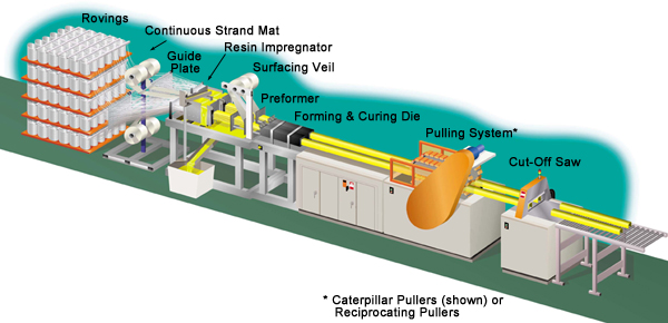
Figure from http://www.acmanet.org/pic/images/schematic.jpg (no longer online)
Click on the image to go to the Pultrusion Industry Council/Composite
Fabricators Association page
Quinn [P1] and Hartley [P2] have produced design manuals for pultruded profiles. Design of pultruded profiles tends to seek uniform thickness in order to achieve uniform cooling and hence minimise residual stress. For the manufacture of hollow profiles, it is necessary to arrange the fibre feed such that a cantilevered mandrel can enter the die from the fibre-feed end.
Applications of pultrusion include panels – beams – gratings – ladders - tool handles - ski poles – kites - hand rails – light poles – electrical insulators and enclosures – roll-up doors. During construction of the Channel Tunnel, 450 km of cable trays were produced by pultrusion. The Maunsell Structural Plastics (MSP) Advanced Composites Construction System (ACCS = interlocking "standard" pultruded box-sections ) was used for the A19 Tees Viaduct deck enclosure, and for the construction of the Aberfeldy Bridge in Scotland and the Bonds Mill Lift Bridge in Gloucestershire (about one mile from the M4 at Junction 13). Hollaway has monitored the creep performance of the Bonds Mill Lift Bridge.
Variants on the pultrusion process include:
Suppliers of
pultrusion machines
Suppliers of
pultruded
sections