Image from http://www.ifm.eng.cam.ac.uk/dstools/gif/ishika.gif
|
Quality Management and Safety Engineering (BSc) - MST 326 Problem solving techniques |
Powerpoint Presentation (383 KB)
BRAINSTORMING (to follow)
MIND MAPS (to follow)
CAUSE AND EFFECT DIAGRAMS (Evans & Lindsay pp 614-616)
The Cause-and-Effect diagram (often referred to as a fishbone diagram or Ishikawa diagram) was introduced by Kaoru Ishikawa as a simple graphical method to record and classify a chain of causes and effects in order to resolve a quality problem. A Cause-and-Effect diagram can be simply prepared by following just four steps [reference 1 citing the QC Handbook by Komatsu Limited]:

Reference
FAILURE MODE AND EFFECTS ANALYSIS (FMEA) (Evans & Lindsay pp 778-779)
Failure Mode and Effects Analysis is:
FMEA requires a thorough knowledge of
For every failure mode at a low level, failure consequences are analysed at
FMEA is usually qualitative but may also be quantitative
FMEA is normally initiated during planning and definition of a project to
investigate qualitative reliability demands of the market
FMEA is used during design and development, for quantitative reliability
activities
FMEA can be used for design reviews
In quantitative design, FMEA may become Failure Mode, Effects and Criticality Analysis (FMECA)
F = probability of failure
A = seriousness (consequences of failure)
U = probability of non-detection before the product or service reaches the customer
It is perhaps easier to remember this in the form used in the motor industry: Severity, Occurrence and Detection (SOD instead of AFU)
Process-FMEA for may be used for
Evans & Lindsay Slide 15: household lamp FMEA
URLs for Failure Mode and Effects Analysis (FMEA) (checked as live on 24 January 2005):
For more complex failures, FMEA may be supplemented by ...
FAULT TREE ANALYSIS (FTA) (Evans & Lindsay pp 779-780)
FTA is a logical chart of occurrences to illustrate cause and effects.
FTA was developed by DF Haasl, HA Watson, BJ Fussell and WE Vesely initially at
Bell Telephone Laboratories then at North American Space Industry.
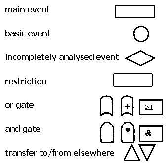
The common symbols used for FTA charts are:

URLs for Fault Tree Analysis (FTA) (checked as live on 24 January 2005):
DESIGN OF EXPERIMENTS (Evans & Lindsay pp 530-534)
Design of Experiments was originally conceived by Ronald Aylmer Fisher at Rothampstead Experimental Station in Hertfordshire during the 1920s where he was analysing plant growing plots under different conditions and needed to eliminate systematic errors. Fisher devised a systematic application of latin and graeco-latin squares to the design of experiments. Latin and Graeco-Latin squares and their application are described in detail at Tony Phillips' Latin Squares in Practice and in Theory I1 - I2 - I3 - I4. A designed experiment enables the experimenter to compare two or more methods to determine which is better or to determine the effects of different levels of controllable factors in order to optimise the yield of a process or minimise the variation due to a response variable.
In cases where a number of factors may influence the output of a process, it may be possible to study all combinations of levels of each factor (a full factorial experiment), but if the number of factors to be considered increases then the number of experiments required increases more rapidly. For two levels of n-variables, the number of experiments required is 2n, i.e. 4 experiments for two variables (low-low, low-high, high-low and high-high) or 16 experiments for four variables or 64 experiments for six variables. Obviously if three levels (low - normal - high) or more are to be studied, then even more experiments are required and solving the problem with a full factorial experiment soon becomes impractical. The results can be plotted to indicate the influence of each of the factors studied. How the change in level of one factor affects the response is known as a main effect. where there exists an interdependence between factors affecting the response, this is termed an interaction.
Genichi Taguchi developed orthogonal arrays (a fractional factorial matrix) that permits a balanced comparison of levels of any factor with a reduced number of experiments. In Taguchi design analysis, each factor can be evaluated independently of each of the other factors. Taguchi's approaches have been used effectively by numerous companies, even though Evans and Lindsay (at page 534) suggest that the approach violates some traditional statistical principles, includes misleading analyses, ignores modern graphical approaches to data analysis and that he failed to advocate randomisation in performing the experiments.
URLs for Design of Experiments (checked as live on 25 January 2007):
Taguchi Designs (Carleton University)
Taguchi Design Tutorial (Design-Ease 6 User Manual)
NJA Sloane, A Library of Orthogonal Arrays
Orthogonal Arrays (Taguchi Designs)
Complementary teaching support materials:
RECOMMENDED TEXTS:
James Evans and William Lindsay, The Management and Control of Quality - Fifth
Edition,
South-Western/Thomson Learning, Cincinnati OH, 2001. ISBN 0-324-06680-5.
PU CSH Library.
inc. CD-ROM with QuickTimeTM videos, web links and spreadsheets. ISBN
0-324-06682-1.