Composites Design and Manufacture (Plymouth University teaching support materials)
Strength. Failure mechanisms. Fractography. Failure criteria. Fracture mechanics. |
Lecture
PowerPoint |
Review
papers |
Subject
Index |
 |
PowerPoint presentation (1.5 MB)
Strength
Strength is the stress at failure and is normally measured in MPa (MegaPascals = MN/m2). Failure may be either a non-reversible change of state
(propagation of cracks within the material) or the ultimate stress where the specimen breaks into two or more pieces.
For a unidirectional composite where the fibres have a lower tensile strain to failure than the matrix, the Kelly-Tyson model [1] (Equation 1) to predict the ultimate strength
assumes that all fibres have identical strength and that both the fibre and the
matrix fail at the failure strain of the fibre:
σ'c = σ'fVf + σm*(1-Vf) (1)
where σc = the ultimate tensile strength of the composite, σf is the ultimate tensile strength of the fibre, σm* is the tensile stress in the matrix at the failure strain of the fibre, Vf is the volume fraction of the fibres and the matrix contains no voids. In many practical situations, the equation can be reduced to σc = σfVf. At low fibre volume fractions, the composite strength may be given by σc < σm#(1-Vf) where σm# is the maximum tensile strength of the matrix.
Kelly and Davies [2] identified three forms of fracture as the fibre direction rotates away from the test direction. For mild misalignment (>x°) of quasi-UD composites, the longitudinal fracture can be modelled using the Kelly-Tyson equation (Equation 2) corrected for the mis-alignment angle θ:
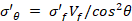 (2)
(2)
At intermediate mis-alignment angles (x°-y°), there may be shear fracture governed by Equation (3), although the fracture mode could transition directly from longitudinal fracture to transverse fracture dependent on the relative magnitudes of the longitudinal, shear and transverse strengths:
 (3)
(3)
where τ’ is the ultimate shear stress (strength) of the matrix. For high misalignment (>y°), there will be transverse fracture (fibre-matrix debonding), governed by Equation (4):
 =
=  (4)
(4)
where σ'T is the ultimate tensile strength of the matrix in plane strain. After the transition from Equation 2 to Equation 3, the composite strength falls rapidly. The critical angle for that transition is tan-1(τ'/σ'θ) . For unidirectional glass fibre/polyester resin composites, measurements from Figure 7.38 in Hull [3] suggest that failure shifts from longitudinal fracture to shear fracture at ~4°, then changes to transverse fracture around ~24° off-axis.
Hart-Smith [4] has proposed an empirical "Ten-Percent Rule" for the preliminary sizing of quadriaxial fibrous composite structures. In it's original form, each 45° or 90° ply was considered to have one-tenth of the axial stiffness and strength of a reference 0° ply. Each 0° or 90° ply was considered to have one-tenth of the in-plane shear stiffness and strength of an equivalent ±45° ply. The in-plane shear strength of a cross-plied laminate can be taken to be one-half of the greater of the (a) tensile or (b) compressive strengths of the complementary (i.e. rotated by 45° fibre) pattern.
Limiting strains in stressed composites
The elongation at break of E-glass virgin filaments is 3.37% with a strength of 3.4 GPa. [5].
When the matrix has a lower failure strain than the fibre, then above the matrix failure
strain, the matrix starts to undergo microcracking and this corresponds with the
appearance of a 'knee' in the stress-strain curve [6].
Hull and Clyne [7] give failure strains for glass fibres, epoxy matrix and polyester matrix
as 2.8%, 2% and 2% respectively. However, when a cross-plied or woven composite
is considered the 'knee' in the stress-strain curve may result from fibre/matrix
debonding and/or transverse cracking in the plies normal to the applied load.
Hull and Clyne (Figure 8.28) indicate a knee-point at ~0.3% strain for a typical
cross-ply laminate in uniaxial tension.
In the design codes for reinforced plastic pressure vessels (BS4994:1987) [8], the following values are given:
- "Debonding occurs at a strain of approximately 0.3% for the resin-glass fibre composites at present in general use".
- "The maximum allowable strain shall not exceed 0.1εR or 0.2%, whichever is the smaller" where εR represents the "extension to failure (fracture strain) of unreinforced resin determined in accordance with Appendix B".
and, for the specific case of filament wound structures:
- "It shall be ensured that the strain transverse to the fibre direction is less than 0.1%".
- "... during hydraulic pressure or static head tests the laminate is at no point strained beyond the limiting values specified in clause 39, i.e. 0.26% or 1.3 εD, whichever is the smaller, where εD is the least strain, determined
from allowable loadings and resin properties".
Failure mechanisms
The principal mechanisms of failure in fibre-reinforced composites are:
- matrix cracking
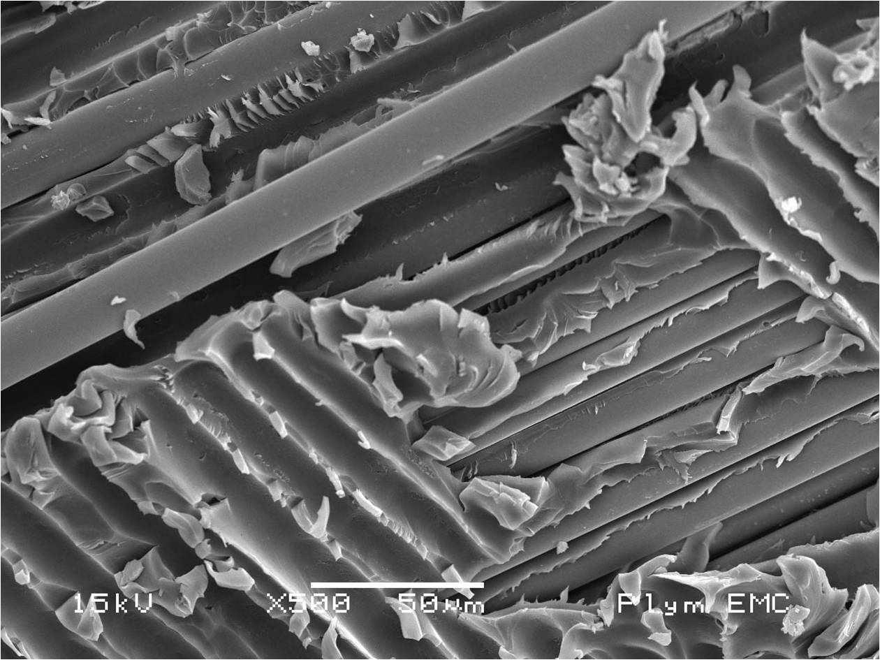
- (fibre-matrix) debonding
- debonding is separation of the fibre from the matrix. The image
shows debonded glass fibres:
- BEWARE: "debonding" is also used to describe the separation of the bulk adhesive from the substrate in an adhesive joint.
- delamination
- delamination is the failure mode in which cracks propagate between the
layers (lamina) of the composite.
- methods to arrest delamination failure (crack arrestors) include:
- 3-D reinforcement (often woven or stitched)
- vertically aligned carbon nano tubes (VACNT)
- Z-pinning
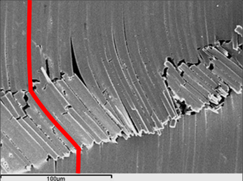
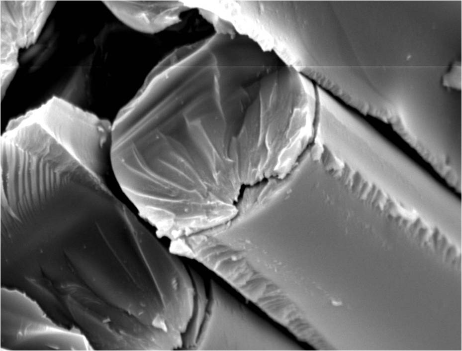
- fibre fracture
- fibre fracture is failure of the reinforcement and normally occurs across the diameter of the fibre.
The image show a glass fibre with (unusually) a double crack running from
the lower edge:
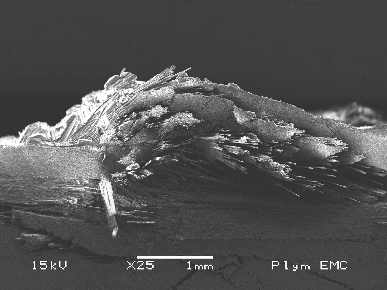
- fibre pullout [8]
- microbuckling
- the image below show microbuckling failure adjacent to the loading anvil
from three-point flexural testing of an 8-ply [-45/90/+45/0]s 1225 gsm quadriaxial stitched non-crimp glass fabric (2 layers) fibreglass/epoxy composite
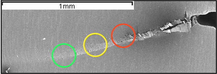
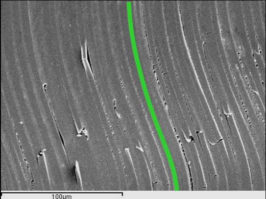
- kink bands (advanced composites only)
- The following images [9] were provided by Soraia Pimenta of Imperial College. The left hand image at low magnification (a) shows the crack propagating from right to left. In consequence, the other images show (b) initial buckling of the fibres, (c) cracking at the lower edge and (d) the fully developed kink-band.
- cone of fracture (carbon fibre composites)
- in this failure, the impacted face shows little or no sign of damage yet delamination occurs in a cone of increasing
diameter until fibres spall from the composite at the back face. This is known in the aerospace industry as BVID
(barely visible impact damage) [10] or barely detectable impact damage. It is normal to encourage reporting of
impacts to permit non-destructive evaluation of the extent of damage. The
United States Federal Aviation Regulation
FAR section
23.573 (Damage tolerance and fatigue evaluation of structure) requires
"that the [composite] structure is capable of carrying ultimate load with
damage up to the threshold of detectability (TOD) considering the inspection
procedures employed" and "the structure must ... be able to withstand
critical limit flight loads, considered as ultimate loads, with the extent
of detectable damage consistent with the results of the damage tolerance
evaluations".
- "Snap buckling"
- When a thick-walled cylinder is subjected to external pressure, any stress concentation (voids or other inclusions) can become the point of crack initiation. The crack is likley to grow under sustained (creep), cyclic (fatigue) or instant (impact) loading. Dependent on the geometry, the inner layers may then snap buckle towards the centre of the cylinder (Figure). Snap buckling was one of the failure modes suggested for the tragic loss of five lives when the OceanGate Titan submersible imploded in June 2023.
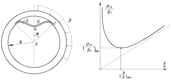
Figure: Snap buckling delamination failure mode and critical load of deep sea thick shell
(from SQ Zhao, Research on compression test of the unidirectional composite material and the failure mechanism analysis,
Harbin Institute of Technology ~ China, 2013. (In Chinese),
via Yongsheng Li et al in Journal of Marine Science and Engineering, 2022, 10(10), 1456).
Imetrum have taken
high-speed (25,000 frames per second) video
(3 MB MPEG file) of the failure of a "carbon composite material" in tension.
Hedgepath [11] undertook theoretical two-dimensional, elastic, small
deformation analyses of stress concentrations arising from fibre fracture in a
sheet of parallel filaments in both static and dynamic loading. The
dynamic stress concentration factor for suddenly induced discontinuities was
found to increase from 1.15 for a single broken fibre to 1.27 for an infinite
number of broken fibres.
Fractography and microstructural characterisation
The following micrographs of fracture surfaces appear in books:
Lothar Engel et al [12]
- page 226 Figure 420: Glass fibre reinforced polyester sample failed under
repeated stress loading. Long sections of glass fibre had been exposed due to
vibration stresses, leaving a matrix perforated by tubes and voids. The
characteristic features of dynamic fatigue fracture are long bundles of glass
fibres protruding from the fracture surfaces. Resin residues adhere to these
bundles. This does not occur if an identical sample is fractured by static
stress.
- page 114 Figure 196 and page 114 Figure 197: The fracture surface of a glass reinforced
polyester specimen was immersed in hydrofluoric acid, which completely
dissolved the glass fibres without attacking the resin
Anne Roulin-Moloney [13]
- page 380
Figure 26: Impact damage - fibre breakage as well as interlaminar and
transverse cracking in a CFRP plate with a high fracture energy matrix.
- page 515
Figure 20: Stress corrosion fracture surface showing directions of crack
propagation
- page 516
Figure 21: Area of stress corrosion fracture surface with crack growth
directions deduced from surface markings. A: nucleation areas. B-B: starter
notch. C: crack growth perpendicular to overall crack growth direction.
- page 519
Figure 23: Mating areas of stress corrosion fracture surface showing
post failure degradation. A: interface failure. B: fibre splitting. C:
loss of fibre end.
- page 45
Figure 1c: A Nomex® honeycomb sandwich core material viewed in the SEM.
Statistical considerations
The failure characteristics of most materials have statistical variability which
is normally better modelled using Weibull statistics [14, 15] instead of normal
distributions. The use of A-Basis and B-Basis allowables to reduce risk in the structural design of composite materials and components has two statistically based tolerance bounds:
- A-Basis or T99: At least 99% of the population of material values is expected to equal or exceed this tolerance bound [16, 17] with 95% confidence (single point catastrophic failure with no-load redistribution),
- B-Basis or T90: At least 90% of the population of material values is expected to equal or exceed this tolerance bound with 95% confidence (redundant load path with load redistribution).
Multi-scale analysis on a hierarchical basis may combine micro-mechanics and macro-mechanics with finite element analysis, damage tracking, fracture and material degradation capability to analyse structures in depth [18].
Failure criteria
BEWARE:
The von Mises (VM) failure criterion is "inherently isotropic, and therefore may yield incorrect results for anisotropic [materials]" [19]. The VM failure criterion is "a good option for ductile materials with equal tensile and compressive strength, but it fails with brittle materials" [20].
The Tresca (maximum shear stress theory) criterion [21, 22] states that a material yields or fails when the maximum shear stress, τmax, reaches a critical value, but the model assumes the material has identical properties in all directions (i.e. isotropic).
Hinton et al [23] and Christensen [24] have provided comprehensive reviews of the many failure criteria for composites. None of these failure criteria are suitable as a single parameter to completely classify the respective composite systems.
Netting analysis [25-27] (often attributed to Puck) was developed to model composite pressure vessels and assumes that only tensile structural loads are carried by the reinforcement fibers, with no structural contribution from the resin matrix. It can be an excellent preliminary design tool, but does not consider off-axis loading (e.g. bending or compression stresses).
The Maximum Stress criterion compares σ11, σ22 and τ12 individually to the axial strength, transverse strength and shear strength respectively. This criterion provides a useful baseline for rapid ply-level assessment of the probability of failure initiation, but should not be assumed to provide a realistic representation of failure. Sun et al [28] found it performed well across bidirectional, off-axis, and pure shear loading.
The Tsai-Hill failure criterion [29] uses a quadratic equation to model the interaction of σ11, σ22 and τ12 as a smooth elliptical failure envelope. It is based on Hill's proposed yield criterion for anisotropic materials, and does not explicitly distinguish between fibre- and matrix-dominated failure. This limits its usefulness when failure mode interpretation is important. Sun et al. [28] found this interactive criteria to underestimate failure and inaccurately predict trends. Kawai and Teranuma [30] found it gave reasonable predictions but noted an inability to distinguish between tension and compression.
The Tsai-Wu failure criterion [31] is a generalization of the tensor failure criterion and gives identical results to Tsai-Hill when the tension and compression allowables have equal magnitude.
The Hashin failure criterion [32] accounts for the simultaneous interaction of multiple stress components with the separation of failure into distint phyical modes as a defining feature. Tension and compression failure modes for either fibre or matrix fracture, cracking or yielding are independently evaluated. This criterion integrates seamlessly with progressive damage models in finite element analysis (FEA) software. Li [33] noted that most real failures do not satisfy the Hashin [29] assumption "It may be argued that in the event that a failure plane can be identified, [then] the failure is produced by the normal and shear stresses on that plane"!
The Hashin-Rotem failure criterion [34] was developed specifically for fatigue, and uses separate functions for σ11, σ22 and τ12. It may be useful as the primary mode-sensitive fatigue criterion for comparison with experimental observations.
The Halpin-Tsai method [35] is not a failure criterion, but is a semi-empirical set of widely used micromechanical equations used to predict/estimate the macroscopic material stiffness (elastic moduli).
Fracture mechanics (for homogeneous isotropic materials)
In the following equations [36]:
Y is a dimensionless parameter or function that depends on both the crack and specimen sizes and geometries, as well as the manner of load application,
σ is the axial stress,
τ is the shear stress in the appropriate plane,
a is the half-crack length,
W is the component width, and
subscript c implies the critical (failure) condition [37].
- direction I is in the plane of the materials with direct stress normal to the crack faces,
- direction II is in the plane of the material with shear stress parallel to the crack
- direction III is out of the plane of the material with shear stress parallel to the crack faces
BE CAREFUL to ensure that the stress axes and the material axes are accurately specified for composite materials.
Also consider whether the failure mode is relevant to the analysis (has the crack turned to run along a fibre/matrix of interlaminar interface)?
Stress Intensity Factor ( Pa.m1/2 )
KI = Yσ√(πa)
KII = Yτ√(πa)
KIII = Yτ√(πa)
Fracture toughness (critical stress intensity factor, Pa.m1/2 )
KIc = Y(a/w)σ√(πa)
KIIc = Y(a/w)τ√(πa)
KIIIc = Y(a/w)τ√(πa)
Strain energy release rate ( J/m2)
GI = KI2 / E
Critical strain energy release rate ( J/m2 )
Gk = Kk2 / E
For a more detailed description, see [37, 38]. For an excellent review of
the subject in the context of composites see the paper by Williams [39].
References
- A Kelly and WR Tyson, Tensile properties of fibre-reinforced metals: copper/tungsten and copper/molybdenum, Journal of the Mechanics and Physics of Solids, 1965, 13(6), 329-350.
- A Kelly and GJ Davies, The principles of the fibre reinforcement of metals, Metallurgical Reviews (now International Materials Reviews), 1965, 10(1), 1-77.
- D Hull, An Introduction to Composite Materials, Cambridge University Press, Cambridge, 1981, page 167. ISBN 0-521-28392-2.
- LJ Hart-Smith, The ten-percent rule, Aerospace Materials, August-October 1993, 5(2), 10-16.
- DR Lovell, Chapter 2A: Reinforcements in NL Hancox, Fibre Composite Hybrid Materials, Elsevier Applied Science, Barking, 1981, page 25. PU CSH Library
- D Hull and TW Clyne, An Introduction to Composite Materials - 2nd edition, Cambridge UP, 1996. PU CSH Library
- British Standard Specification for Design and Construction of Vessels and Tanks in Reinforced Plastics, BS 4994 : 1987 (British Standards Institution, London).
This standard "covers part of the field, namely, the use of polyester, epoxy and furane resins in wet lay-up systems". BS4994 is generally accepted to provide a safe, but often over-engineered solution!
- F Teklal, A Djebbar, S Allaoui, G Hivet, Y Joliff and B Kacimi, A review of analytical models to describe pull-out behavior ~ fiber/matrix adhesion, Composite Structures, 1 October 2018, 201, 791-815.
- R Gutkin, ST Pinho, P Robinson, PT Curtis, Physical mechanisms associated with initiation and propagation of kink-bands, 13th European Conference on Composite Materials (ECCM13), Stockholm, 2 June 2008.
- KB Armstrong and RT Barrett, Care and Repair of Advanced Composites, SAE International, Warrendale PA, 1998. ISBN 0-7680-0047-5. Second edition, 2005. PU CSH Library.
- JM Hedgepath, Stress concentrations in filamentary structures, NASA Technical Note TN-D-882, 20 March 1961.
- Lothar Engel, Hermann Klingele, Gottfried W Ehrenstein and Helmut Schaper (translated by MS Welling), An Atlas of Polymer Damage: Surface Examination by Scanning Electron Microscope, Wolfe Science Books, London, 1981. ISBN 0-7234-0751-7. UOP
Library
- Anne C Roulin-Moloney, Fractography and Failure Mechanisms of Polymers and Composites, Chapman & Hall (originally Elsevier Applied Science), London, 1988. ISBN 1-85166-296-0. PU CSH Library
- S van der Zwaag, The concept of filament strength and the Weibull modulus, Journal of Testing and Evaluation, September 1989, 17(5), 292-298.
- P Kittl and G Diaz, Weibull's fracture statistics, or probabilistic strength of materials: state of the art, Res Mechanica, 1988, 24(2), 99-207.
- R Rice, R Randall, J Bakuckas and S Thompson, Development of MMPDS Handbook Aircraft Design Allowables, 7th Joint DOD/FAA/NASA Conference on Aging Aircraft, New Orleans LA, 8-11 September 2003.
- DOT/FAA/AR-03/19, Final Report: Material Qualification and Equivalency for Polymer Matrix Composite Material System: Updated Procedure, US Department of Transportation Federal Aviation Administration - Office of Aviation Research, Washington DC, September, 2003.
- MR Talagani, Z Gurdal, F Abdi and S Verhoef, Obtaining A-Basis and B-Basis allowable values for open-hole specimens using virtual testing, AIAAC-2007-127, 4. International Aerospace Conference, Ankara, 10-12 September 2007
- CE Korenczuk, LE Votava, RY Dhume, SB Kizilski, GE Brown, R Narain, VH Barocas, Isotropic failure criteria are not appropriate for anisotropic fibrous biological tissues, Journal of Biomechanical Engineering, July 2017, 139(7), 071008 (10 pages). Paper BIO-16-1518.
- A Pérez-González, JL Iserte-Vilar and C González-Lluch, Interpreting finite element results for brittle materials in endodontic restorations, BioMedical Engineering OnLine, 2011, 10, article 44.
- HÉ Tresca, Mémoire sur l'écoulement des corps solides soumis à de fortes pressions (Memoir on the flow of solid bodies subjected to strong pressure), Comptes Rendus hebdomadaires des séances de l'Académie des Sciences, 1864, 59, 754-758.
- Jean Salençon, About Tresca's Memoirs on the fluidity of solids (1864–1870), Comptes Rendus Mécanique, 2021, 349(1), 1-7.
- MJ Hinton, AS Kaddour and PD Soden, Failure criteria in fibre reinforced polymer composites: the world-wide failure exercise, Elsevier, Amsterdam, 2004. ISBN 0-08-044475-x.
- Richard M Christensen, Stress Based Failure Criteria for Materials Science and Engineering, 2008, and specifically III: Failure Criteria for Anisotropic Fiber Composite Materials.
- A Puck, Calculating the strength of glass fibre/plastic laminates under combined load, Kunststoffe/German Plastics, 1969, 55, 18–19. German text at pages 780–787.
- TT Chai, Design for commercial filament winding, SPE Journal, 1966, 22, 43.
- DK Roylance, Netting analysis for filament-wouund pressure vessels, Army Materials and Mechanics Research Centre report AMMRC-TN-76-3, Wayertown MA, August 1976.
- C Sun, BJ Quinn, J Tao and DW Oplinger, Comparative evaluation of failure analysis methods for composite laminates, Office of Aviation Research report DOT/FAA/AR-95/109, Washington DC, May 1996. DTIC AD A310352.
- SW Tsai, Strength characteristics of composite materials, NASA Contractor report CR-224, Washington DC, 1965. DTIC AD A307777.
- M Kawai and T Teranuma, A multiaxial fatigue failure criterion based on the principal constant life diagrams for unidirectional carbon/epoxy laminates, Composites Part A: Applied Science and Manufacturing, August 2012, 43(8), 1252-1266.
- SW Tsai and EM Wu, A general theory of strength for anisotropic materials, Journal of Composite Materials, 1971, 5(1), 58-80.
- Z Hashin, Failure criteria for unidirectional fibre composites, Transactions of ASME: Journal of Applied Mechanics, June 1980, 47(2), 329-334.
- S Li, A feeble cornerstone of modern composite failure criteria: the Mohr's criterion and its undue extension to composites, 3rd China International Congress on Composite Materials, Xiaoshan/Hangzhou - China, 21 October 2017.
- Z Hashin and A Rotem, A fatigue failure criterion for fibre reinforced materials, Journal of Composite Materials, 1973, 7(4), 448-464.
- JC Halpin and JL Kardos, The Halpin-Tsai equations: a review, Polymer Engineering and Science, May 1976, 16(5), 344-352.
- WD Callister, Materials Science and Engineering - An Introduction - fifth edition, John Wiley & Sons, New York, 2000. ISBN 0-471-32013-7. Eighth edition, 2011. PU CSH Library.
- Chapter 9: Analysis of Fracture, in RF Gibson, Principles of composite material mechanics, McGraw-Hill, 1994, pages 338-373. ISBN 0-07-023451-5. Third edition, 2012. PU CSH Library.
- RJ Sanford, Principles of Fracture Mechanics, Prentice Hall, New Jersey, 2003. ISBN 0-13-092992-1. PU CSH Library.
- JG Williams, Fracture mechanics of composite failure, Proceedings of the Institution of Mechanical Engineers Part C: Journal of Mechanical Engineering Science, 1990, 204(4), 209-218.
Recommended further reading
- Lothar Engel and H Klingele, An atlas of metal damage: surface examination by scanning electron microscope. Wolfe, London, 1981. ISBN 0-7234-0750-9.
- Lothar Engel, H Klingele, GW Ehrenstein and H Schaper (translated by MS Welling), An atlas of polymer damage: surface examination by scanning electron microscope, Wolfe Science/Hanser, Munich, 1981. ISBN 0-7234-0751-7.
- AJ Kinloch and RJ Young, Fracture Behaviour of Polymers, Chapman & Hall (originally Elsevier Applied Science), London, 1983. ISBN 0-85334-186-9.
- JG Williams, Fracture Mechanics of Polymers, Ellis Horwood Series in Engineering Science, Chichester, 1984. ISBN 0-85312-685-2.
- AC Garg and Yiu-Wing Mai, Failure mechanisms in toughened epoxy resins: a review, Composites Science and Technology, 1988, 31(3), 179-223.
- AC Roulin-Moloney,- Fractography and failure mechanisms of polymers and composites, Elsevier, London & New York, 1990. ISBN 1-85166-296-0. PU CSH Library
- WD Bascom and SY Gweon, Fractography and failure mechanisms of carbon fibre-reinforced composite materials, Chapter 9 in AC Roulin-Moloney (see above).
- Kimberley Dransfield, Caroline Baillie and Yiu-Wing Mai, Improving the delamination resistance of CFRP by stitching—a review, Composites Science and Technology, 1994, 50(3), 305-317.
- MR Piggott - The effect of fibre waviness on the mechanical properties of unidirectional fibre composites: a review, Composites Science and Technology, 1995, 53(2), 201-205.
- Myer Ezrin, Plastics Failure Guide: Causes and Prevention, Hanser-Gardner Publications, Cincinnati, 1996. ISBN 1-569-90184-8. Carl Hanser Verlag, München - Germany, 1996. ISBN 3-446-15715-8. PU CSH Library
- GJ Simitses - Buckling of moderately thick laminated cylindrical shells: a review, Composites Part B: Engineering, 1996, 27(6), 581-587.
- J Summerscales, Microstructural Characterisation of Fibre-Reinforced Composites, Woodhead Publishing, Cambridge, July 1998. ISBN 1-85573-240-8. PU CSH Library
- Holger Thom - A review of the biaxial strength of fibre-reinforced plastics, Composites Part A: Applied Science and Manufacturing, 1998, 29(8), 869-886.
- T Kant and K Swaminathan, Estimation of transverse/interlaminar stresses in laminated composites: a selective review and survey of current developments, Composite Structures, 2000, 49(1), 65-75.
- LN McCartney, Physically based damage models for laminated composites, Proceedings of the Institution of Mechanical Engineers - Part L: Journal of Materials: Design & Applications, 2003, 217(3), 163-199.
- AO Addin, SM Sapuan, E Mahdi and M Othman, Prediction and detection of failures in laminated composite materials using neural networks - a review, Polymers and Polymer Composites, 2006, 14(4), 433-441.
- S Sridharan, Delamination behaviour of composites, Woodhead Publishing, Cambridge, 2008. ISBN-13: 978 1 84569 244 5.
- ES Greenhalgh, Failure analysis and fractography of polymer composites, Woodhead Publishing, Cambridge, 2009. ISBN 978-1-84569-217-9.
Return to MATS 347 home page
Updated by John Summerscales on 03-Jun-2026 12:34. Terms and conditions. Errors and omissions. Corrections.
 c:
c: 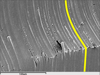 d:
d: