Resin Transfer Moulding (RTM)
PowerPoint
papers
Index

| Composites Design and Manufacture (Plymouth University teaching support materials) Resin Transfer Moulding (RTM) |
Lecture PowerPoint |
Review papers |
Subject Index |
|
DVD: Advanced techniques of light resin transfer molding (Doug Smith), American Composites Manufaturers Association, 2008. PU CSH Library 668.412ADV 28'28" DVD.
Liquid Composite Moulding (LCM) is a generic term for a variety of closely related manufacturing processes where liquid reactants are caused to flow into fibre reinforcement contained in a mould tool or enclosed by a bag. The processes include:
LCM normally uses thermosetting resin systems, as thermoplastic melt viscosities are too high. To produce thermoplastic matrix composites, in-situ polymerisation may be appropriate.
The resin transfer moulding (RTM) process
For the manufacture of complex components with two moulded surfaces, the resin transfer moulding (RTM) process is the usual choice. The reinforcement fibres (usually as layers of a woven or non-crimp fabric) are placed into a mould which defines the net-shape of the component. Inserts, fixing points and lightweight core materials can all be incorporated at the moulding stage. The mould is closed before resin is injected to fill the inter-fibre spaces. Once the resin has cured, the component (either net-shape or requiring only minimal trimming) is removed from the mould. The process can produce components with superior dimensional tolerances to hand-lay/autoclave products, whilst reducing worker and environmental hazards by eliminating uncontrolled emissions of volatile materials.
Most other composite manufacturing process involve only short range flow of the resin into the fibre tow or through the layer thickness. RTM differs from other composite manufacturing processes as it involves long-range flow of resin, parallel to the laminae, through the porespace between the reinforcement fibres. The scientific principles and the technology of the process [1-7] and the governing equations have been well described elsewhere [8, 9].
Key Equations for Liquid Composite Moulding (LCM) Processes
The volumetric flow rate (units: m3/s) of a fluid in a saturated porous medium is given by the Darcy equation [10]
Q = K.A.ΔP/μ.L
where K is a constant of proportionality known as the permeability (units: m2), A is the cross section of the porous medium normal to the flow direction (units: m2), ΔP/L is the pressure gradient driving the flow (units: Pa/m) and μ is the fluid viscosity (units Pa.s. Note that 1 Pa.s = 1000 mPa.s = 1000 centipoise).
Composite systems are anisotropic so the equation should have tensor form. Liakopoulos [11] proved that the permeability tensor is symmetric and of second order. Neumann [12] used a formal averaging procedure to demonstrate that Darcy's law for anisotropic porous media is a special form of the Navier-Stokes equation.
The permeability, K, can be predicted using the Kozeny-Carman [13, 14] equation:
Q = ε.A.m2.ΔP/k.μ.L
where ε is the porosity (1-Vf), m is the hydraulic radius, and k is the Kozeny constant.
Blake [15] defined the hydraulic radius as the volume in which fluid actually flows, εV (where V = AL), divided by the wetted surface area (S):
m= ε.V/S
∴ Q = ε3.A.V2.ΔP/k.μ.S2.L
Until fibres touch, the increase in surface area [16] will be linear with volume fraction (Vf2 is substituted for S2).
∴ K α (1-Vf)3/Vf2 or ε3/(1-ε2)
Aktas et al [17] have surveyed the procedures used for permeability measurements in liquid composite moulding processes. The experimental determination of the permeability of reinforcement textiles is the subject of an international benchmarking exercise [18-21] which aims to standardise measurement methods and interchangeability of results. Good practice guidelines are being formulated to eliminate sources of scatter in the data.
Bodaghi et al [22] used additive manufacture to produce three dimensional reference porous media for the calibration of permeability measurements. Statistical analysis of 20 permeability measurements under set conditions returned a coefficient of variation <2%, confirming the elimination of the inherent variability associated with real reinforcement stacks. Bodaghi et al [23] have presented insights from a multi-participant computational study coordinating the international benchmarking of permeability predictions in anisotropic reference porous media. Dei Sommi et al [24] have presented an overview of the measurement of permeability for composite reinforcements and described new trends towards reliable methods based on non-invasive and integrated sensors.
Summerscales [25] and Park and Krawczak [26] have considered the differences in permeability reported for the same fabrics between saturated (fully wetted) and unsaturated (with a flow front as in LCM processes) conditions. Kim et al [27] and Diallo et al [28] have reported that saturated permeabilities are always lower than unsaturated permeabilities. This suggests that the change in surface energy during wetting dissipates some energy. However, other authors have reported opposite results [29-33]. Gibson et al [34] have reported that air permeability varies as a function of relative humidity due to swelling for hygroscopic fibers such as cotton, wool, silk, and nylon.
Swelling of fibres
The absorption of the permeant fluid by natural fibre reinforcements, and the consequent fibre swelling increases the fibre diameter and has been suggested as the principal reason for inconsistencies in permeability measurements for these reinforcements [35, 36]. Nguyen et al [37, 38] investigated the influence of liquid absorption and fibre swelling during RTM resin impregnation of flax fibre reinforcements and suggested a relationship between fibre swelling and permeability:
K = (1 - fSW2 Vf) n+1 / A (fSW2 Vf) n
where K is the permeability, fSW is the fibre swelling ratio (wet diameter/dry diameter), Vf is the fibre volume fraction and A and n are empirically derived constants. The progress of the resin flow front may be delayed if swelling of the fibres behind the flow front constrains liquid moving forwards or may have a favourable effect by forcing resin forwards. These opposing effects should be included in the mass conservation equation using sink and source terms. In consequence, the permeability value may need to vary with exposure time and position in the preform. Nguyen used models with varying permeability (mass source/sink terms) which lead to better agreement with the experimental flow measurements than the constant permeability model. When the fibre volume increased, the effect from the mass sink became greater.
Straumit et al [39] have used X-ray micro-computed tomography registration with statistical image segmentation of the textile internal architecture to calculate a correct (within the experimental scatter) homogenised textile reinforcement permeability for a non-crimp fabric using computational fluid dynamics with voxel geometrical models.
Fabric compressibility
Quinn and Randall [40] suggested that fabric compressibility could be modelled using the following equation:
Vf = K1 + K2.√P
where K1 and K2 are constants and P is the applied pressure, while Toll and Månson [41, 42] and Toll [43] offer the following generic equation:
P = kE(Vfn - Vfon)
where k is a power-law coefficient, E is the elastic modulus of fibres, Vf is the fibre volume fraction, Vfo is the limiting fibre volume fraction (below which P = 0) and n is a power-law exponent.
Characterisation of the materials
The use of RTM as an economic and efficient means of producing high performance fibre-reinforced composites is critically limited by the permeability of the fabrics employed. This parameter relates the fluid flow rate to the pressure gradient, the fluid viscosity and the dimensions of the bed of porous medium. A highly automated apparatus for the measurement of reinforcement permeability was developed at Plymouth in the context of an 11-partner research project funded by the European Union (programme BE5477) to support the development and evaluation of a software simulation package for the process. In this permeameter, a fabric stack is located in a mould with an upper glass face. Resin is introduced through a central injection port in the aluminium mould base. The progress of the resin front is monitored by a video camera and the image is sampled at regular time intervals using a computer frame-grabber. The computerisation of the analysis reduces the time for parameter calculation significantly whilst simultaneously permitting additional data validation [44]. The associated theory has been derived in a novel way using scaling of variables and the frame of invariance of vectors [45].

Permeability data from BRITE/EurAM II project BE5477 (1992-1996) Download 35KB .xls file
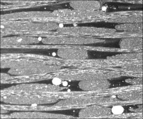
The rate of flow of the resin through the fabric can be increased by clustering of the fibres to produce "flow-enhancing tows". Satin weave reinforcement fabrics which exploit this concept are marketed as Injectex® by Hexcel Composites/Brochier SA in France [46]. The micrograph below shows a section from an Injectex fabric-reinforced plate. The two different tows can be distinguished: normal tows have an aspect ratio of 8:1 whilst the flow-enhancing tows have an aspect ratio of <3:1. The white areas are voids in the polished surface which have been filled with talc to discriminate them from voids below the surface. Clearly there is significant pore space (the dark resin rich area plus the void area) adjacent to the flow-enhancing tows to promote faster mould filling.
Carr Reinforcements (UK) supplied experimental twill weave fabrics with differing proportions of normal and flow-enhancing tows. The permeability of these fabrics was measured and correlated to quantitative descriptors of the microstructure of the resulting composite plates [47-49]. The permeability of the laminates was found to increase with the number of flow enhancing tows present. However, the introduction of the initial tows was far more effective than the benefit gained by the introduction of further tows.
Further, both the compression and inter-laminar shear strengths of these laminates were measured and found to decrease with an increase in the proportion of flow-enhancing tows [50]. The Engineering and Physical Sciences Research Council (EPSRC grants GR/J77405 and GR/K04699) funded subsequent work to attempt to resolve this process-property dilemma. The "new concept Carr fabrics" appeared to achieve appropriate process-property-structure relationships for commercial application, i.e. they showed flow enhancement with minimal reduction in mechanical properties [51]. The fabric architecture was characterised by determination of the fractal dimension (a single number to describe the degree of clustering in the microstructure) and this parameter showed a correlation to permeability and to tensile strength.
Chomarat G-Flow™ [52] is a structural flow medium developed to have very high permeability while maintaining mechanical performance. Company information.
Practical considerations for the RTM process
Resin: In RTM, the resin flows long distances in comparison to most other processing techniques. Rudd et al [2] suggest that the most significant practical limitation on the suitability of a resin system is imposed by viscosity. Note that a low viscosity indicates high flow rate whilst a high viscosity indicates low flow rate. Resins with extremely low viscosity may be unsuitable for LCM processes as they may result in high porosity or gross voidage. Resins formulated for liquid composite moulding processes typically have an initial viscosity around 200 mPa.s (1 mPa.s = 1 centipoise). Becker [53] quotes an upper limit for viscosity in RTM of 800 mPa.s. The non-injection point (NIP) is defined as a viscosity of 1000 mPa.s [54]. The flow front is effectively stationary at this viscosity and the low pressures used in infusion processes.
Molten thermoplastic polymers typically have viscosities far in excess of those used for RTM. However, in recent years there has been increasing use of in-situ polymerisation to produce thermoplastic matrix composites by RTM albeit usually at elevated temperatures. The principal systems are caprolactam (e.g. DSM Fiber intermediates APA-6) to produce polyamide 6, laurolactam (e.g. EMS-Grivory APLC12) to produce polyamide 12 and cyclic butylene terephthalate oligomers (e.g. Cyclics Corporation) to produce PBT polyester. Pang et al [55] have reviewed the polymerisation of polyesters using cyclic oligoesters as the precursor material and van Rijswijk and Beukers [56] have reviewed in-situ polymerisation of most polymers in this context. The Arkema Elium® liquid thermoplastic resins include formulations specifically designed for RTM/infusion manufacture of composite parts with similar welding and recycling characteristics to thermoplastics.
Resin delivery may be achieved by pumping individual components from separate containers (mixing is often achieved by static mixers in the resin feed line) or the resin may be premixed and fed to the mould from a pressure pot (compressed air above the resin drives it through the feed lines into the mould). There are two basic approaches: constant flow rate with variable pressure (usually via pumps) or constant pressure with variable flow rate (pressure pot). It may be advantageous to introduce the initial resin at low pressure/flow rate in order to minimise "fibre wash": when a viscous fluid meets a low permeability porous medium, the reinforcement may suffer significant displacements rather than permeated. In extreme cases, this can result in "easy flow paths" which permit resin to reach the vents before the reinforcement is fully impregnated and this can lead to dry patches in the component.
Where vacuum is to be used in the process, it is important that the resin is degassed (usually under vacuum) to an appropriate level before it is introduced to the mould cavity.
Reinforcement: In order to minimise the mould open time, it is normal to preform the reinforcement before it is loaded into the mould. This may be achieved by a variety of means, but usually involves some form of binder (e.g. adhesive powder, threads or nets (Crenette or Spunfab)) to hold the various layers in position. Ideally the binder will dissolve into the resin matrix during the flow processes. Marquart [57] has reported that preforming may consume 70% of costs for RTM components.
Mould tools: It is important that the mould tool is sufficiently stiff to resist the hydrostatic pressures of the process. Mould deflection can again lead to "easy flow paths" which may in turn produce dry spots in the component. A similar problem may arise where the reinforcement pack does not completely fill the mould cavity. Any gaps at the edges will lead to "race tracking" of the resins along these routes. With careful design, this feature can be used to generate "galleries" which feed the resin to specific positions in the mould.
For mould tools which are operated only with positive pressure, the mould edges may be allowed to leak resin. In some cases, the reinforcement can be placed over the seals to provide a path for air to escape along the periphery of the moulding. For mould tools where a vacuum is used, it is important that the tool has vacuum integrity (no paths for air ingress through the tools itself). In some vacuum systems a peripheral channel is used, at higher vacuum than that in the cavity, in order to clamp the mould halves together.
Other forms of mould clamping include mechanical (eg Plastech dowels and toggles) or pneumatic and hydraulic press systems.
Void formation and transport
The flow processes involved in RTM may differ dependent on the pressures used. At low pressures, capillary forces may cause transport of the resin primarily within the fibre bundles. At the pressures more normally used for RTM (1-5 atmospheres), the resin tends to fill the inter-tow spaces first with subsequent impregnation of the interior of the tow. In the latter case, the moulding may appear to be completely filled but the resin can then "drain" into the tows resulting in characteristic resin shrinkage marks or internal/surface voids - this is often referred to as the "sink effect". If the resin outlet is closed and pressure is maintained on the inlet until cure is complete, then good surface finish may be achieved.
Hayward and Harris [58] studied the effect of vacuum used in RTM. They observed that the application of a vacuum significantly aided fibre wetting and that it was the vacuum alone that was responsible for this improvement. If the injection pressure was raised to achieve the same pressure differential as when using vacuum assistance, then it might be expected that the same improvement in fibre wetting would be seen but this was not the case. In one of their experiments, the vacuum was pulsed several times during injection: areas of improved fibre wetting directly correlated to times when the vacuum was applied. The areas of poorer wetting were not improved by any subsequent application of vacuum. They conclude that the effect of the vacuum is confined to the flow front.
For unsaturated polyester resins, Lundström et al [59, 60] state that styrene must be subjected to 10 mbar absolute of vacuum at 40ºC for it to be evolved from the resin system. Elsewhere [61], the vapour pressure of styrene at 20ºC is quoted as 6 mbar. Dreyer et al [62] give vapour pressures of 8.2 and 13.7 torr [10.93 and 18.27 mbar respectively] at 29.9ºC and 39.2ºC respectively while Chaiyavech et al [63] give vapour pressures of 13.33 and 26.66 at 32.4ºC and 45.6ºC mbar respectively. Lundström et al [59, 60] believe that porosity is not due to the "boiling" of styrene but, in most cases, is due to poor mould sealing which allows air to leak into the mould cavity and they suggest that double seals should be used with a higher vacuum drawn between the seals than in the mould.
Lundström et al [59] investigated the problem of void formation by concentrating on VARTM. They state that possible methods of void formation are entrapment of air already in the mould and void growth after nucleation due to various mechanisms. One method of entrapment is related to the different permeabilities in the fibre tows and pore space. During infusion the resin will flow around the tows before permeating into the tows. As pressure in the surrounding resin increases the void is compressed thus enabling resin to penetrate further until equilibrium is achieved. Experimental panels were produced with Vf of 59%. In all cases a pressure differential of 0.5 MPa was maintained between the inlet and outlet regardless of the vacuum level used. On subsequent analysis of the plates they found that the region with significant void content was located at the flow front but that with increasing vacuum this region became smaller whilst the void content also dropped. This agrees with the findings of Hayward and Harris [58]. Using the ideal gas law and several assumptions they state that the effect of the vacuum is to make any entrapped bubbles smaller and thus more likely to be swept away or dissolved.
Lundström observed that flow front regions have a higher void content. Lundström and Gebart [64] further studied the effect of process parameters on void formation by conducting similar experiments to those above in a clear topped RTM mould cavity with dimensions of 880 x 160 x 3 mm. Micrographs of sections cut from the panels revealed two distinct types of void:
They found that void content increased with increasing flow lengths but that void content could be reduced by continuing resin flow after initial mould fill, thus ‘washing’ voids out of the mould. It was observed that bubble velocity was 1/5th of the resin velocity. The effect of temperature was examined whilst maintaining the 0.5 MPa pressure differential over a flow length of 0.4m. It was observed that void content increased with increasing temperature despite decreasing resin viscosity but that the ‘bubbly’ region at the flow front was relatively constant. They suggested that the mechanism for this might be thermal expansion of the voids but this was deemed unlikely as both mould and fibres were allowed to reach thermal equilibrium. An alternative explanation might be the evolution of volatile components. In further experiments they conducted constant flow rate experiments at two values of viscosity (190 mPas @ 35ºC and 65 mPas at 50ºC). It was found that constant flow with the higher viscosity shortened the void region. They also conducted an experiment at a lower pressure differential (0.17 MPa) at 35ºC and found that compared with the higher pressure differential injections the total void content was approximately the same but these voids were more evenly distributed rather than being concentrated at the flow front as found in the higher pressure differential injections.
A simple experiment consisting of two capillary tubes (0.4 and 0.6 mm diameter) placed vertically in beaker with a thin layer of resin in the bottom indicated that surface tension effects were found to be negligible as the temperature increased. Surface treatments were found to significantly affect void content: fibres with the sizing removed became ‘softer’ and easier to spread which could possibly lead to better filling. Increasing pore space complexity was found to produce higher void contents due to an increase in complex flow paths as would be expected.
Stringer [65] reported that degassing of resin prior to the wet lay-up vacuum bagging process alone was not sufficient to produce panels with low void content. He also observed that vacuum was beneficial in void reduction.
It has been shown that the angle at which flow fronts converge can lead to increased voidage [66]. This reference also reported increasing void content with increasing temperature. Their main conclusion is that vacuum is the parameter that has the most benefits with regards to laminate quality since fewer voids were found at high vacuum.
Lundström [67] simulated void transport in RTM by studying bubble transport through capillary tubes. He found that the pressure required to deform bubbles through a constriction is set by the ratio of the constriction radius and the tube radius, the length scale of the geometry, liquid surface energy and in certain cases the contact angle of gas-liquid-solid interfaces. He considered three scales in the RTM process, fibre, tow and mould. Dependent on the size of the channel, he found that the pressure required to transport voids may be high and often resulted in trapped intra-tow voids.
Abraham and McIlhagger [68] investigated various methods of liquid resin injection to achieve minimal void content (for aerospace applications). These methods were for positive-pressure or vacuum-infused panels with either radial or peripheral gating. Vacuum infusion with peripheral gating gave the lowest void content, fast wet out and highest flexural strength. They commented that vacuum impregnation produced the thinnest panels since the mould is deflected inwards rather than outwards as would be the case with positive pressure RTM.
Chen et al [69] conducted visualisation experiments in tow wetting. Oil was infused into a transparent rigid mould under pressure. Bubbles clearly showed as black against a semi-transparent background. Unidirectional mats and woven roving were used in an as received condition. Fluid velocity was 1.3 mm/s and was estimated at this value by averaging the superficial velocity, i.e. the macro velocity throughout the entire mould. They identified three stages of air entrapment: initial fibre/resin contact and bypassing, liquid penetration after bypassing and air bubble mobilisation. Liquid penetration into the tows was found to be dependent on the liquid invading speed. Voids were found to move axially along fibres until they find a pore space to escape into or settle down or merge with another void. They identified three types of voids compared to the two identified by Lundström et al. These were, long cylindrical voids inside the tows, meso voids that encompass many fibres inside the voids (inside fibre bundles) and spherical macro voids outside fibre bundles. The spherical bubbles were found to be the ones that accumulate at the end of the mould. Voids were found to shrink when subjected to pressure but not necessarily become mobilised.
Edu Ruiz (verbal presentation by École Polytechnique Montréal at FPCM-8) suggested that for the same configuration, same filling time and same capillary number, the void content is uniform when mould is filled at the optimum constant flow rate, but increases with distance from the injection point when injected at constant pressure.
Process Simulation
Gebart [70] evaluated alternative injection strategies for RTM:
Zhong Cai [72] presented a simplified RTM process analysis based on the one-dimensional resin flow model by using Darcy's law for flow through porous media. Closed form solutions were derived for the wet length, mould filling time and pressure distributions for simplified mould shapes (rectangular, trapezoidal, circular). On the basis of the analysis, he proposed that:
"When the real process is close to the constant applied pressure boundary condition at the inlet, the saving in filling time is significant by these arrangements. Also line gates are better than point sources".
Cai [73] extended the mould filling simulation with mould sections decomposed as a combination of simple geometric shapes (as above with the addition of spheric or conic sections) and developed closed form solutions for each of these shapes. The flow was modelled using Darcy's law with either Newtonian or power-law fluids. This approach greatly reduced computer time and user interface effort compared with more sophisticated simulation programs. Total mould filling time could be estimated, as well as the required inlet pressure or flow rate.
There are a number of software packages which can be used to model resin transfer moulding:
EUROS Germany used PAM-RTM in the development of a process strategy for the production of an 80 m long wind turbine rotor blade using Vacuum Assisted Resin Infusion (VARI) [74]. The software was used to minimise process risks whilst reducing manufacturing time, assuring process repeatability and achieving optimum product quality.

Alternative modelling techniques might include:
Component studies
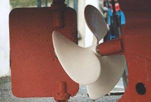
Four designs of marine propellers up to 660 mm diameter (photograph below) were manufactured in the context of a doctoral research programme. Sea trials have been carried out on a 500 mm diameter three-bladed composite propeller installed on a 7-metre work boat with a 40 hp diesel engine. Experiments to measure top speed and the thrust generated with the stern of the boat tied to a bollard have demonstrated that the new propellers give similar performance to traditional bronze propellers [76, 77]. The composite propeller was designed as a retrofit and did not attempt to exploit the potential benefits of hydro-elastic tailoring of the blade material. Tentative finite element models were generated to predict the potential hydrodynamic advantage which may result from such tailoring of the blades by selective fibre placement.
The first monolithic thick-section composite panels representative of an armoured fighting vehicle (AFV) were produced at the University of Plymouth using RTM [78]. These included a 1 metre square single curvature panel with thickness increasing across the panel from 35 mm at one edge to 60 mm at the opposite side. The panels weighed almost 100 kg. They were supplied to the Defence Research Agency and subjected to severe ballistic threats. The sponsors announced that a demonstrator glass-reinforced plastics fighting vehicle with similar section thicknesses would be built using RTM [79]. The ACAVP hull is made from E-glass, a glass-fibre reinforced-plastic composite manufactured by Vosper Thornycroft, while Vickers assembled the vehicle and completed the necessary vehicle safely checks prior to delivery to DERA for full scale trials [80, including photograph below]. The vehicle is currently at the Tank Museum and regularly gets an outing at shows [81].

At present there is no genuine mass production process available for complex composite components. This has held back their adoption in volume markets. Resin transfer moulding offers considerable potential for automation [82] and the cycle time can be reduced to minutes when the process is used with optimised raw materials. A modular roof-tile panel has been produced as a demonstrator component for RTM automation systems.
Plastech lead a consortium to provide the infrastructure (mould tools and RTM equipment) to re-equip the Sri Lankan fishing fleet after the devastation caused by the Indian Ocean tsunami on 26 December 2004. (NetComposites report, HTML & ITV West Country News report, 1m 37s Windows Media Video 9).
Abraham and McIlhagger [83] have reviewed liquid injection techniques for the manufacture of aerospace composite structures. Mouton et al [84] have described a procedure to assist in the industrialisation of the resin transfer molding (RTM) process for composite aerospace components in the context of design for manufacturing (DFM). They used a multi-expertise approach to optimise parts integration while considering the location and number of gates or vents required to use the RTM manufacturing process for a spar from a horizontal plane of the Falcon aircraft.
Other typical components include Lotus car bodies, Beneteau yachts, British Rail High Speed Train cabs, Dowty aircraft propellers and Chelton radomes.
References
Further reading: