Pre-preg/moulding compounds. Vacuum bag. Autoclave. Diaphragm moulding. Compression moulding.
PowerPoint
papers
Index

| Composites Design and Manufacture (Plymouth University teaching support materials) Pre-preg/moulding compounds. Vacuum bag. Autoclave. Diaphragm moulding. Compression moulding. |
Lecture PowerPoint |
Review papers |
Subject Index |
|
Pre-impregnated (pre-preg) reinforcement
The health and safety implications of thermosetting resin systems are a major consideration when the resin is in the liquid state (A-stage, i.e. not cross-linked). As cure progresses through light cross-linking the chemicals become less able to migrate into the body. At this B-stage, the resin may be swollen by solvents but will not dissolve. Full cross-linking (complete cure) is known as the C-stage. Further, by mixing and pre-impregnating the resin at the materials suppliers, the risk of incorrect resin preparation on site is eliminated. Thermoset prepreg materials are impregnated using immersion or similar techniques and the resin is taken to B-stage. It is then necessary to store the material in a freezer (typically at -20ºC) to retard the cure of the resin.
Because the cure of thermosetting resin prepreg systems has been initiated, they have a finite shelf life. They are normally supplied with a use-by date after which they should not be used for any application which may result in injury, loss or damage. The time the roll of the material is out of cold storage will reduce its useful life (out-life) and should be recorded. It is normal to allow the material to warm to ambient temperature before use as condensation may form on the material when cold. Prepreg epoxy systems normally fall into one of three categories:
Key characteristics of prepreg materials are the drape (formability) and tack (stickiness). These two parameters are neither well-defined nor easily measured. Crossley et al [1] used an existing British Standard for pressure sensitive adhesives as a starting point to develop a new peel test which quantifies tack and dynamic stiffness of uncured prepreg. The new method includes a pressure controlled application stage where contact time is inversely proportional to peel rate (simulating automated tape laying processes). ASTM International have published a Standard Test Method for Characterizing Tack of Prepregs Using a Continuous Application-and-Peel Procedure (ASTM D8336-21).
During the lamination of prepreg materials it is normal to debulk the materials every few layers by subjecting the stack to vacuum in a temporary bag or on a vacuum table. Hexcel claim that "Carbon fiber panels made with no debulking revealed approximately three times less porosity than those using a typical 10 minute debulk with every second ply" when using the new G-Vent technology.
Unsaturated polyester resins are not normally used for pre-pregging. However, an equivalent system is the group of materials known as thermoset moulding compounds which are normally supplied "just in time" for the production of composite components usually by compression moulding. These compounds are marketed in three major forms:
Thermoplastic matrix prepregs may be prepared by melt or solvent or powder or commingling techniques. A popular form is Glass-Mat Thermoplastic (GMT) where continuous random swirl (Unifilo) glass fibre sheet is preimpregnated with normally polypropylene (PP) or polyamide (PA), polybutylene terephthalate (PBT) and other polymers.
Video: What are prepregs? (Society of Manufacturing Engineers on YouTube)
Compressibility of reinforcements
Quinn and Randall [2] have suggested that Vf is a function of the square root of pressure, P (Table 1):
| Fibre | Fabric | Equation | %Vf @ 1.55 Int atm |
| E-glass | continuous strand mat | Vf = 9.7 + 0.37√P | 24 |
| E-glass | chopped strand mat | Vf = 20 + 0.46√P | 38 |
| E-glass | roving | Vf = 32 + 0.75√P | 62 |
| E-glass | woven fabric | Vf = 40 + 0.45√P | 58 |
| E-glass | woven roving | Vf = 21 + 0.60√P | 45 |
| Kevlar | fabric | Vf = 47 + 0.51√P | 67 |
| Carbon | unidirectional cloth | Vf = 34 + 0.80√P | 66 |
| Carbon | ±45° fabric | Vf = 35 + 0.51√P | 55 |
Toll and Månson [3] proposed the equation: P = kE(Vfn - Vfon), where:
The data in Table 2 is from Toll and Månson [3-5]:
| Fibre | kE | Vfo % | n | Reference |
| wool | 13 | 1.45 | 3 | J Schofield [6] |
| wool | 420 | 2 | 3 | CM van Wyk [7] |
| planar | 4500 | 3 | 5 | S Toll et al [8] |
| spun glass roving | 820 | 8.5 | YR Kim et al [9] | |
| fluffy glass roving | 260 | 7 | YR Kim et al, 1991 [9] | |
| straight glass roving | 700 | 15.5 | YR Kim et al [9] | |
| graphite roving | 500 | 14.5 | YR Kim et al [9] | |
| mat | 115 | 3.5 | R Gauvin & Chibani [10] | |
| mat | 100 | 4.5 | JA Quinn and Randall [2] | |
| weave | 500 | 11 | YR Kim et al [9] | |
| weave | 8 | 7 | R Gauvin & Chibani [10] | |
| weave | 15 | 9 | JA Quinn and Randall [2] |
Pearce and Summerscales [11] summarised these values of the exponents above as 3 for 3D wads, 5 for the random planar case, 7-11 for weaves and 7-15.5 for rovings. For a 625 g/m2 plain weave E-glass they found values of the exponent between 4.8 and 8.8 for initial loading to 300 kPa.
Francucci [12] used the Freundlich equation (from the Origin scientific graphing and data analysis software where a, b and c are empirical parameters.):
to model the compression response of fabrics and found it to better represent the response than the exponential function or the power law.
Kirschnik et al [13] reported that "[g]lass fiber composites exhibit a higher fibre volume content [than flax fiber composites under similar process conditions]". The MATS347 composites were manufactured by students on the "with composites" pathway at University of Plymouth.
| Fibre | Matrix | Vf (%) | Reference |
|---|---|---|---|
| Glass fibre | |||
| 580 gsm twill weave glass (GF1) | Ep+TETA | 58% | Kirschnik et al [13] |
| 352 gsm twill weave glass fibre | Easy Composites IP2 polyester resin | 57% | AY2024-25 MATS347 Group B |
| 395 gsm plain weave glass (GF2) | Ep+TETA | 53% | Kirschnik et al [13] |
| 292 gsm twill weave glass fibre | Easy Composites IP2 polyester resin | 57% | AY2024-25 MATS347 Group G |
| 295 gsm plain weave glass fibre | Easy Composites IN2 epoxy resin | 48% | AY2024-25 MATS347 Group H |
| 282 gsm plain weave glass fibre | Easy Composites IN2 epoxy resin | 46% | AY2024-25 MATS347 Group D |
| Carbon fibre | |||
| 238 gsm twill weave carbon fibre | Easy Composites IN2 epoxy resin | 47% | AY2024-25 MATS347 Group E |
| 251 gsm twill weave carbon fibre | Easy Composites IN2 epoxy resin | 47% | AY2024-25 MATS347 Group F |
| 249 gsm twill weave carbon fibre | Easy Composites IP2 polyester resin | 42% | AY2024-25 MATS347 Group I |
| 217 gsm twill weave carbon fibre | Easy Composites IN2 epoxy resin | 43% | AY2024-25 MATS347 Group C |
| 218 gsm twill weave carbon fibre | Easy Composites IP2 polyester resin | 42% | AY2024-25 MATS347 Group A |
| Flax fibre | |||
| 500 gsm twill weave flax (NF) | ELSO/IA/Zn | 42% | Kirschnik et al [13] |
| 500 gsm twill weave flax (NF) | ELSO/IA | 40% | Kirschnik et al [13] |
| 500 gsm twill weave flax (NF) | BEp+IA | 40% | Kirschnik et al [13] |
| bEp = bio-epoxy, ELSO = epoxidised linseed oil, Ep = epoxy, IA = itaconic anhydride hardener, TETA = triethylenetetramine hardener, Zn = zinc-based salt catalyst | |||
When a composite is made by wet lay-up (hand lamination) or spray techniques it is generally resin rich and hence of low fibre volume fraction. The fibre volume fraction, and hence mechanical properties, can be improved by bleeding off excess resin. To achieve this the laminate is enclosed by a polymeric film sealed to the mould edges. A breach unit penetrates the bag and permit a vacuum to be drawn in the bag. This imposes a consolidation pressure of up to ~1000 mbar on the materials in the bag. The principal disadvantage of this technique is the disposable materials that are included in the bag (Figure 1 and Table 4).

Figure 1: Schematic of the vacuum bagging process (linked from http://www.netcomposites.com/images/Fig_5-3a.jpg,
reproduced here with the permission of SP
Systems Limited and NetComposites)
[14]
| Peel-ply | A sacrificial open weave fibreglass or perforated heat-set nylon ply placed between the laminate and the bleeder/breather to provide the textured and clean surface necessary for further lamination or secondary bonding. |
| Bleeder cloth | A non-structural fabric designed to absorb excess resin and reactants from the laminate. This may also act as the breather cloth. |
| Breather cloth | A loose weave or non-woven porous material use to provide a gas flow path over the laminate both to permit the escape of air, reactants, moisture and volatiles and to ensure uniform vacuum pressure across the component. This may also act as the bleeder cloth. |
| Release film | A (perforated) sheet of material placed between the laminate and the mould surfaces to prevent adhesion. |
| Edge dams | Profile used to define the edge of the component |
| Caul plate | A mould or tool placed on top of the laminate inside the bag to define the second surface. |
| Intensifiers | Generally hard rubber profiles incorporated in the bag to consolidate the laminate at sharp radii. |
| Bagging film | The membrane which permits a vacuum to be drawn within the bag. |
| Tacky tape | Adhesive strip used to bond the bag to the tool and provide a vacuum seal. |
| Breach unit | A connector through the bagging film to permit a vacuum to be drawn. |
| Vacuum pipes | The link between the breach unit and the vacuum pump. |
| Resin trap | A container in the vacuum line to collect any excess resin before it can damage the vacuum pump. |
| Vacuum pump | Generally a high-volume pump (absolute vacuum is rarely required) suitable for continuous running. For some slow-curing epoxy resins twenty-four operation may be needed. |
| Pressure gauges | Generally clock-type or digital gauges attached via a breach unit connection. |
The recommended reading material for this topic is Cripps et al [13] and the West System guide [15]. Note that either peel ply or porous release film may be used for the same purpose.
Stringer [16] considered the wet lay-up/vacuum bag process and concluded that the viscosity at the start of the vacuum bag consolidation was the critical parameter in the achievement of high fibre volume fraction and low void content carbon fibre/epoxy resin composites. It was concluded that a dwell time window "exists between the same viscosity limits regardless of the resin system and temperature being used". For carbon fibre composites, up to 58% fibre by volume and less than 2% void content by volume were obtained with the dwell time window corresponding to 7500-16500 mPas (75-165 poise).
Video: the vacuum bag moulding and curing process (Society of Manufacturing Engineers on YouTube).
Tube rolling (mandrel wrapping) is a technique where pre-preg blanks are formed onto a mandrel and consolidated normally using shrink-wrap. The process is most often used to manufacture fishing rod blanks. Tube rolling companies include Hardy Advanced Composites and Kilwell FibreTube (New Zealand)
Autoclave curing (see also Åström pp 215-217)
It is only possible to apply ~1000 mbar pressure with a vacuum bag process on its own. In order to achieve greater levels of consolidation it is normal to use an autoclave. For composite structure manufacture, an autoclave is a pressure vessel with pipework to allow a vacuum to be maintained in the bagged work-piece (e.g. Figure 2). Temperature control is normally by gas- or electric-heating with a proportional-integral-derivative (PID) controller. Ciriscioli and Springer [17] have presented some initial ideas for an expert system for smart autoclave cure. Cooling may be achieved through the introduction of liquid nitrogen to the vessel at the end of the process cycle.
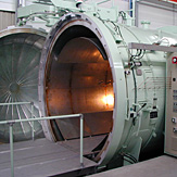
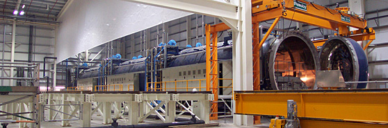
Figure 2: Autoclaves from Aeroform Limited (from http://www.aeroform.co.uk/), reproduced here with the permission of the company
This is a pressure vessel which permits precise control of the internal temperature and pressure (Figure 3). The combination of vacuum within the bag and pressure outside the bag ensure good consolidation and assist in making the laminate conform to tight radii. The gas in the autoclave may be air for low temperature curing resin systems, but an inert gas (often nitrogen) is used at higher temperatures to slow the deterioration of seals and to minimise the risk of fire.
Figure 3: A typical cure schedule for an epoxy matrix prepreg composite
A related, relatively inexpensive, technology is the pressclave. This is normally a hinged frame with an elastomeric membrane which permits vacuum to be drawn under the membrane via perforations in the pressclave base and external pressure to be applied outside the membrane.
Corebon have introduced the CoreClave 5-minute autoclave which uses a one-sided induction-heated tool and applies up to 12 bar of pressure with compressed air or nitrogen. It is claimed to ensure exceptional part quality with unparalleled speed and efficiency.
Suppliers of autoclaves
Diaphragm moulding (see also Åström pp 286-290)
Diaphragm Forming (DF) is an autoclave technique used solely for thermoplastic matrix composites. The laminate is laid up flat between two diaphragms (superplastic aluminium sheets or high-temperature polymeric films), the diaphragms are clamped in a frame (the laminate is not clamped), then the laminate is formed using heat, vacuum and pressure in the autoclave. The (normally female) mould may be relatively deep compared to other processes and permits vacuum to be drawn under the laminate stack. Autoclave pressure is then applied to consolidate the laminate. In some variants of the process the clamping frame may also permit the application of vacuum without resort to an autoclave for pressurisation. A major disadvantage of the process is that the diaphragms are normally a disposable item, although rubber membranes may be used a number of limited times. A number of papers in the scientific literature discuss wrinkling in this process.
Compression moulding (see also Åström pp 273-277)
In compression moulding, two matched (usually steel) mould halves are mounted in a (normally hydraulic) press with movement limited to the axis normal to the plane of the mould. This process tends to be associated with a variety of materials, including (but not an exhaustive list):
The moulds may be heated or the composite may be preheated and formed in relatively cool moulds. A limitation on the process is the uniaxial force applied - as a consequence while horizontal surfaces are subject to compression loads as the component surfaces change to vertical there is little or no component of the force acting to consolidate the material in that plane. Further near vertical surfaces may be subjected to wrinkling during mould closure. These issues may be resolved by the use of rubber-block moulding or hydroforming (pressurised liquid contained in a flexible membrane) wholly or partially substituting the male mould half.
References
Further reading