Reinforcement fibres.
PowerPoint
papers
Index

| Composites Design and Manufacture (Plymouth University teaching support materials) Reinforcement fibres. |
Lecture PowerPoint |
Review papers |
Subject Index |
|
Contents (in alphabetical order, with links to section headings)
| Fibre | Trade/generic names | Year of introduction of continuous fibres |
| Aramid fibres | Kevlar, PPTA, Twaron | 1972 |
| Basalt fibres | 1923 | |
| Boron fibres & 2020 | 1966 | |
| Carbon Fibres | 1968 | |
| Glass Fibres | 1937 | |
| Natural fibres | flax, hemp, jute, kenaf | 32,000 BCE |
| Polyethylene fibres | Dyneema, Spectra | 1987 |
| Surface treatments on fibres |
Fibres for the reinforcement of composites (or other uses such as ropes) can be sourced from a variety of different routes (Table 1).
Glass fibres were known in ancient Phoenician and Egyptian civilisations. Renaissance Venetian glass workers in the 15th-16th century used glass fibres to overlay bottles [1]. Commercially important continuous-glass fibre filaments were manufactured in 1937 by a joint venture between Owens-Illinois and Corning Glass. The Owens-Corning company is still a major producer of reinforcement.
A variety of fibre compositions are available for different purposes:
The principal ingredient is usually silica (SiO2) with the addition of other oxides. The differences in the above fibres result from the other constituents of the composition (Table 2).
| Oxide | E-glass [2] | S-glass [2] | Basalt rock [3] | Effect on Fibre Properties |
| SiO2 | 55.2 | 65 | 52.8 | very low thermal expansion |
| CaO | 18.7 | trace | 8.6 | resistance to water, acids and alkalis |
| Al2O3 | 14.8 | 25 | 17.5 | improved chemical durability |
| B2O3 | 7.3 | trace | - | low thermal expansion |
| MgO | 3.3 | 10 | 4.6 | resistance to water, acids and alkalis |
| Na2O | 0.3 | trace | 3.3 | high thermal expansion, moisture sensitivity |
| K2O | 0.2 | - | 1.5 | high thermal expansion, moisture sensitivity |
| Li2O | - | - | - | high thermal expansion, moisture sensitivity |
| Fe2O3 | 0.3 | trace | 10.3 | green colouration |
| ZnO | - | - | - | chemical durability |
| PbO | - | - | - | increased density and brilliance (light transmission) and high thermal expansion |
| BaO | - | - | - | high density and improved chemical durability |
| TiO2 | - | - | 1.4 | improved chemical durability especially alkali resistance |
| MnO | - | - | 0.2 | |
| P2O5 | - | - | 0.3 | |
| Cr2O3 | - | - | 0.06 | |
| F2 | 0.3 | - | - |
These glasses are usually amorphous, although some crystallisation may occur after prolonged heating at high temperatures. The modulus and strength of the glass are determined primarily by the three-dimensional structure of the constituent oxides. The silica usually occurs in tetrahedral bonding as shown below.
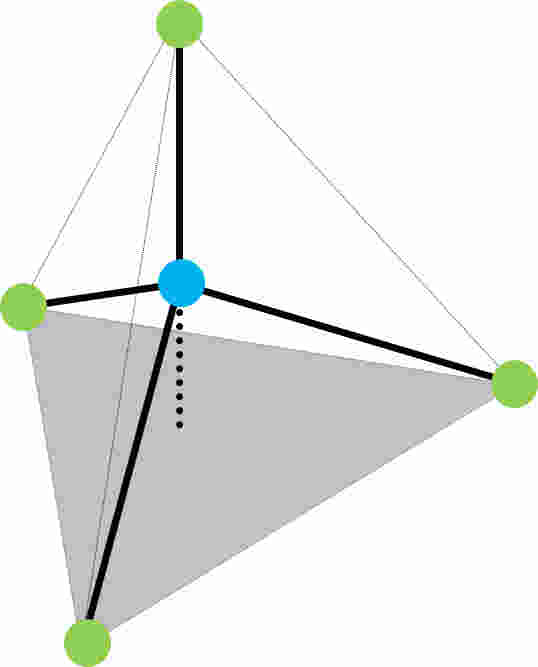
Figure 1: The SiO4 tetrahedron (green = oxygen, blue = silicon) which is the basic building block of many glasses.
but rather than forming a linear structure, a random sequence of Si-O bonds leads to the amorphous polyhedron network, which is further disturbed by the introduction of other oxides as shown in the Figure:
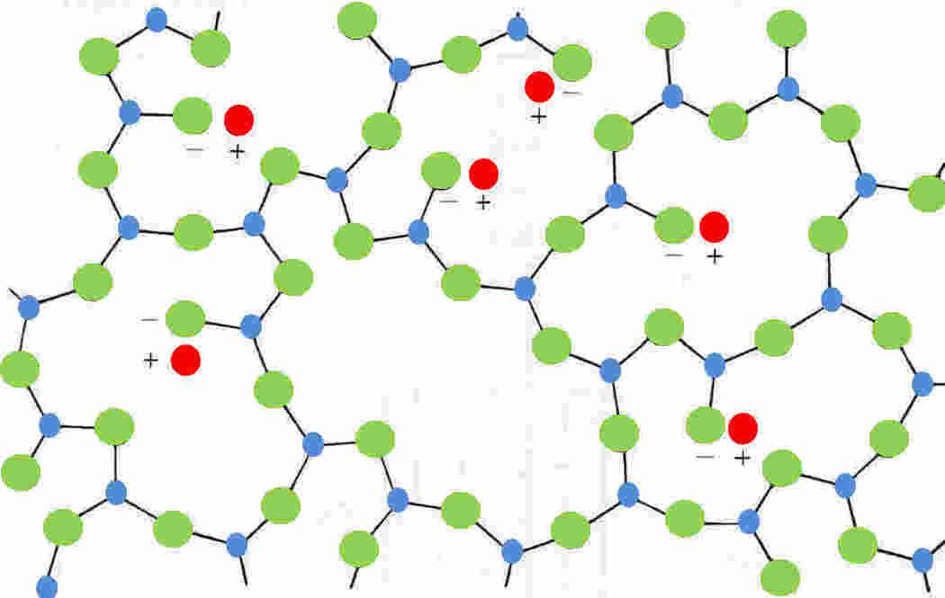
Figure 2: A two-dimensional representation of the three-dimensional structural network in a sodium silicate glass
NB: red= sodium, green = oxygen, blue = silicon and silicon is shown with only
three-bonds but will have a fourth bond out-of-plane (after Hull 1981 edition Figure 2.7 [4]).
Makishima and Mackenzie [5] have proposed an equation for the direct calculation of the Young's modulus of oxide glasses from their chemical compositions. Their analysis suggests that the moduli should lie in the range 41 GPa (for 45% SiO2, 65% Pb0) to 160 GPa (for BeO, Al2O3, ZrO2 glass). Capps et al [6] have produced a glass with a modulus of 145 GPa (26.2% SiO2, 18% Al2O3, 28.6% MgO, 27.2% BeO). Glass fibres are normally assumed to be isotropic. Stockhorst and Bruekner [7] have shown a very small preferred orientation of bridging oxygen atoms in the glass fibre axial direction, and of non-bridging oxygen atoms perpendicular to the axis. For all practical purposes, the Young’s modulus along the fibre can be assumed to be the same as that in the transverse direction.
Continuous filament fibres are produced by melting the raw materials (sand, limestone, boric acid, clays and fluorspar) generally at around 1260ºC. The molten material is fed into a series of low corrosion metal (Pt) bushings with a multitude of holes in the base. The glass flows under gravity and fine filaments are drawn. The filament diameter is controlled by the hole size, temperature, melt viscosity, cooling rate and method. The hot filaments are quenched by water or air and wound onto drums at several thousand metres/minute. Surface coating (sizing) and drawing (stretching) may occur in the winding stage. For a more comprehensive description of the manufacture of glass fibres, see Gardiner [8].
Table 3 summarises the principal commercial forms of glass fibre. There is also a R-FiberTM radiation-resistant glass fibre under development at Nanjing Fiberglass R&D Institute.
| Fibre | Density (kg/m3) | Young's modulus (GPa) | Virgin filament strength (MPa) | Roving strength (MPa) | Strain to failure (%) |
| A (alkali) | 2460 | 73 | 3100 | 2760 | 3.6 |
| C (chemical) | 2460 | 74 | 3100 | 2350 | ~ |
| D (dielectric) | 2140 | 55 | 2500 | ~ | ~ |
| E (electrical) | 2550 | 71 | 3400 | 2400 | 3.37 |
| R (reinforcement) | 2550 | 86 | 4400 | 3100 | 5.2 |
| S (strength) | 2500 | 85 | 4580 | 3910 | 4.6 |
| S2 | 2460 | 90 | 3623 | ~ | ~ |
| S3 | 2830 | 99 | 3283 | ~ | ~ |
A chemical known as the "size" is applied to fibre surfaces to guard against abrasion during the mechanical handling stages, especially in subsequent weaving processes. Thomason [10] has published a review of the scientific literature on glass fibre sizings. The size is multi-functional and may:
The initial size may be temporary with the first four function and may subsequently be replaced by a "coupling agent" to promote good bonding between the fibre and the composite matrix (although this is not normally commercially viable). Coupling agents are molecules which have one end compatible with the silicon of the glass fibre and the other end is compatible with the matrix. Typically these surface treatments would be poly(vinylacetate) modified with a methacrylic chromic chloride complex and/or an organosilane coupling agent. The region between the fibre and the bulk resin is known as the interface, or as an interphase where preferential orientation of the molecule occurs.
The first person to delve into the realm of material imperfections was Alan Griffith in 1920 [11], following studies of the strengths of glass rods and fibres. He found that when the diameter decreases to about 10 micrometres (the typical diameter of an individual filament of glass reinforcement), the strength of the fibre becomes markedly higher than that of a thick rod. Assuming that such thin fibres must be free of the flaws that plague thicker specimens, Griffith analysed the energy balance at idealised cracks and its dependence on applied stress. When a crack grows there is an increase in energy due to the new surface generated accompanied by an energy decrease in the release of the stress. The surface energy is proportional to the crack area, but the stress relief is proportional to the crack volume. Doubling the crack diameter causes a four-fold increase in crack area but an eight-fold increase in crack volume. The total mechanical energy around a crack can thus be lowered by crack growth, and ultimately sample failure. The density of mechanical energy is related to the applied stress. A critical stress level exists above which a crack of a given size will spontaneously propagate. For small cracks, the critical stress level is higher. Griffith’s very fine fibres were strong simply because any cracks in them would necessarily have been very small. Griffith’s work was the key to the present understanding of brittle fracture in all materials. The strength of the modern fibreglass industry is "a fitting memorial to his pioneering efforts".
Fibre tensile strength is highly dependent on surface defects and therefore the shorter the sample tested, the higher the strength (the lower the statistical probability of finding a significant flaw!). The effects of surface cracks can be minimised or removed by etching the surface but this is not a commercial proposition.
Basalt [3, 12] is igneous or metamorphic rock from volcanic magma and flood volcanoes. Very hot (semi-)fluid material from within the earth's crust solidifies as it reaches the cooler open air. The material is typically a mixture of three minerals: plagioclase (Tc = 1010°C), pyroxene (Tc = 830°C) and olivine (Tc = 720°C). The mineral colour is normally from dark grey to black, although basalt fabrics can appear a natural golden brown. Man-made basalt fibres require no secondary materials (unlike glass fibres), are liquified and melt-drawn at 1500°C (glass melt point is 1400-1600°C) and have a relative density of 2.8-2.9. The fibres have Young's modulus of 79-93 GPa, strengths of 3.0-4.8 GPa and elongation at break of 3.1%. They can withstand temperatures up to 700°C and are resistant to strong alkalis (>pH 13) and strong acids that would cause severe damage in glass fibres.
Carbon fibres [13] were used by Thomas Edison for his electric light bulb, but high-stiffness/high-strength fibres did not become available until the 1950s and continuous fibres have only been available since the late 1960s. Carbon occurs naturally in two forms: as a highly organised sp3-bonded tetrahedral crystal (diamond), and as a planar sp2-bonded system of interconnected hexagonal rings (graphite) with delocalised electrons above and below the plane.
Carbon fibres are based on layered structures of hexagonal rings, similar to the “graphene” structure of graphite. “Graphite fibres” is used in America to denote high-modulus carbon fibres with a Young’s modulus in excess of 400 GPa.
In single crystal graphite, the hexagonal arrays are stacked in a regular ABAB sequence. The hexagonal rings are held together by very strong covalent bonds. The interlayer forces are much weaker van der Waal’s bonds. The basic crystals are highly anisotropic with:
The carbon-carbon bond lengths in the hexagonal arrays are 0.142 nm, and the interplane spacing is 0.335 nm.
High-modulus, high-strength carbon fibres have diameters of 7-8 μm and consist of small crystallites of “turbostratic” graphite. The layers have no regular stacking sequence and the average spacing between the planes is 0.34 nm. To obtain high modulus and strength, the layer planes of the graphite must be aligned parallel to the fibre axis. X-ray and electron microscope studies have indicated that the average straight dimensions of the stacks of graphite in fibres are typically less than 10 nm.
The modulus of carbon fibres depends on the degree of perfection of the alignment. Imperfections in alignment results in complex shaped voids elongated parallel to the fibre axis, which act as stress raisers and points of weakness. The alignment varies considerably with the manufacturing route and conditions. High-modulus fibres are those which have been subjected to heat treatment in excess of 1650ºC, possess three-dimensional ordering of the atoms, have carbon contents above 99 percent (although their graphitic structure is still less than 75%) and have a tensile modulus above 350 GPa.
Figure to follow (e.g. Brent Strong [14] page 57 Figure 3-4 .. this page is under construction)
The principal precursor materials for carbon fibres are:
The main manufacturing routes impose orientation by:
For a more comprehensive description of the manufacture of carbon fibres, see McConnell [20].
The tensile properties of carbon fibres (Table 4) are strongly affected by the manufacturing parameters: the precursor material, heat treatment time-temperature-tension, surface treatments, and surface or internal flaws. It should be noted that the high modulus materials have very low strain-to-failure (elongation at break), and in the case of PAN-based fibres the tensile strength is also sacrificed. This fibre develops a scaly or onion-skin surface during heat treatment to increase the modulus. The onion-skin surface worsens the bonding to the matrix. Improved manufacturing methods are reducing this problem.
| Precursor: | PAN | Torayca T1200 |
PAN | Torayca M46X |
Pitch | Pitch | Rayon | Pitch (K13D2U) |
|---|---|---|---|---|---|---|---|---|
| Modulus: | Low | Intermediate | High | High | Low | High | Low | ultrahigh |
| Tensile modulus (GPa) | 231 | 315 | 392 | 437 | 161 | 385 | 41 | 935 |
| Tensile strength (GPa) | 3.4 | 8.0 | 2.5 | 5.0 | 1.4 | 1.8 | 1.1 | 3.7 |
| Strain to failure (%) | 1.4 | 2.5 | 0.6 | 1.1 | 0.9 | 0.4 | 2.5 | 0.4 |
| Relative density | 1.8 | 1.82 | 1.9 | 1.84 | 1.9 | 2.0 | 1.6 | 2.2 |
| Carbon assay (%) | 94 | ~ | 100 | ~ | 97 | 99 | 99 | >99 |
Carbon fibres are moderately good conductors of electricity. This is assumed to be due to the mobility of the delocalised electrons above and below the plane of the hexagonal array and the alignment of the graphene rings with the fibre axis. Electrical conductivity typically increases with increasing Young’s modulus. Considerable research is underway to improve the conductivity of carbon fibres, especially using “intercalation” (the insertion of guest species between the slip planes of the crystals).
The longitudinal coefficient of thermal expansion of carbon fibres is slightly negative and this increases in magnitude with increasing modulus. This contraction can be balanced with the positive coefficient of other reinforcements (eg glass) or in the matrix resin to produce a material with a coefficient of thermal expansion of zero.
In 2015, the Hypetex® introduced "coloured carbon fibres" to the market. However, the intellectual property documentation [21] suggests that the system is a carbon fibre composite with a cosmetic surface layer!
Carbon fibre manufacture normally requires fossil-based feedstocks and has a high embodied energy. The Technical University of Munich [22-24] has proposed the use of natural, non-genetically modified algal feedstock to produce acrylonitrile precursor for carbon fibres from the glycerin by-product of biodiesel production without fossil materials. The PAN-fibers are passed through the focal line of a mirror where direct solar power heats them to furnace temperatures. and with a net extraction of CO2 from the atmosphere.
Aramid is a term derived from poly aryl amide, the chemical structure being alternated aromatic (aryl) benzene rings and the amide (CONH) group. The commercial reinforcements fibres are Kevlar (DuPont) and Twaron (Akzo) which are believed to be poly(para-phenylene terephthalamide) [PPTA] as in the Figure below. The polymer is produced by the elimination of hydrogen chloride from terephthaloyl chloride and para-phenylene diamine. The polymer is washed and dissolved in sulphuric acid to form a partially-oriented liquid crystal solution. The solution is spun through small die holes, orientation taking place in the spinnerette, and the solvent is evaporated. Hull suggests that the solution is maintained between -80ºC to -50ºC before spinning and is extruded into a hot walled cylinder at 200ºC.
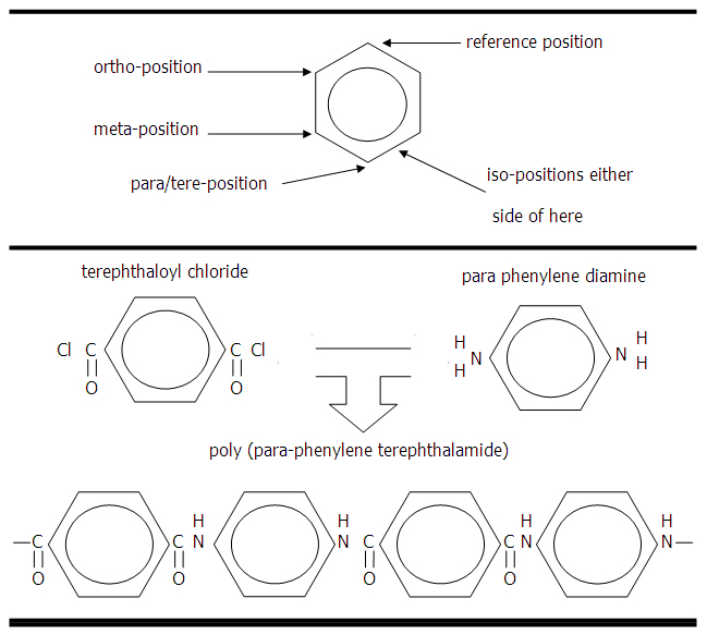
Figure 3 (upper): Naming of the positions around the benzene ring.
Figure 3 (lower): Chemiscal precursosrs and product for poly(para-phenylene terephthalamide).
Kevlar was introduced for commercial products in 1971. There are three principal types of Kevlar fibre (Table 5):
| Fibre type | E (GPa) | σ' (GPa) | ε' (%) | |
| Kevlar 29 | high-toughness, high-strength, intermediate modulus for tyre cord reinforcements |
83 | 3.6 | 4.0 |
| Kevlar 49 | high modulus high-strength for composite reinforcement |
131 | 3.6 | 2.8 |
| Kevlar 149 | ultra-high modulus recently introduced |
186 | 3.4 | 2.0 |
A closely related aramid material is poly(meta-phenylene isophthalamide) which is produced as single spun yarns and used in the manufacture of "paper" for honeycomb cores. The commercial versions are Nomex (DuPont) and Conex (Teijin).
In addition to the strong bonds along the chain, hydrogen bonding (indicated by the blue broken lines in the diagram below) occurs between the amide groups (specifically the carbonyl group (C=O) in one chain and the amine group (NH) in the adjacent chain):
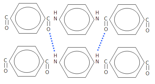
Figure 4: Hydrogen bonding in aramid fibres.
The high aromatic content of the polymer gives good thermal and strength properties, and the linear bonding combined with the hydrogen bonding gives excellent rigidity. The aramids are less brittle than carbon or glass fibres and process a combination of good strength, low weight and high toughness. The coefficient of thermal expansion is negative in the fibre direction.
The molecular structure of Kevlar 49 has been studied by electron diffraction and dark field electron microscopy [25]. The molecules form rigid planar sheets with the chain-extended molecules hydrogen bonded together. The sheets are stacked to form a crystalline array but there is only weak bonding between the sheets, which are arranged in a radial system of axially pleated lamellae. Each component of the pleat is about 500nm long and they are separated by short transitional bands. The angle between adjacent components of the pleat is about 170º.
Fibres with this structure are likely to have low longitudinal shear modulus and poor transverse properties. Kevlar has very low resistance to axial compression, typically around 20% of the corresponding tensile strength. When the fibres fail, they break into small fibrils which are like fibres within the fibre. The fibrils arise from the rod-like structure of the liquid crystal.
In addition to the problems in compression, Kevlar fibres are hygroscopic (they absorb water) and the surfaces are susceptible to degradation by ultraviolet light.
Other rigid-rod polymers include the poly benz[x]azoles (PBX). The principal groups are PBI (poly(benzimidazole)), PBO (poly(benzoxazole)) and PBT (poly(benzthiazole)).
Polyethylene fibres, made from ultra-high molecular weight polyethylene (UHMWPE), have been recently introduced under the trade names Dyneema (DSM) and Spectra (Allied Corporation). They have excellent strength-to-weight and modulus properties. The strength and modulus are similar to those of the aramids. The density of polyethylene is lower than that for the aramids so the weight specific properties of PE are superior and almost match those of high-modulus carbon fibres
The fibres have a melting point below 150ºC, and hence composite manufacture can present difficulties, particularly if the reinforcement is used with high-exotherm thermosets or high-performance thermoplastic matrix systems. There have been recent developments in which hot compaction has been used to melt the less crystalline surface layers of such fibres, followed by hot compaction to produce polyethylene fibre reinforced polyethylene.
Natural fibres for the reinforcement of polymer matrix composites are normally the bast fibres (the structural fibres from plant stems). This topic is dealt with in a separate unit of this module (A9 natural fibres). The most common bast fibres used in this way are flax, hemp, jute and kenaf. Click here for a list of journal articles for a broader range of natural fibres (bamboo, coir, flax, kenaf and sisal).
Surface treatments on fibres exist for a variety of reasons:
Acknowledgements
This document was generated using ScanSoft Dragon Naturally Speaking voice recognition software Standard Version 6.00
with subsequent proof-reading !
References
Further reading