PowerPoint
Lists
papers
Index

| Materials selection for (marine) composites |
Lecture PowerPoint |
Reading Lists |
Review papers |
Subject Index |
|
Composites Design and Manufacture: brief overviews
1 Introduction
The salt water environment of the seas and oceans is corrosive to most engineering metals and, in combination with marine animals such as the naval shipworm (Teredo navalis), and gribble (Limnoriidae) causes rapid deterioration of wood. In consequence, the excellent properties of fibre-reinforced polymer matrix composites, using the continuous fibres which became available during the middle of the twentieth century, have come to dominate the materials of choice for marine structures.
The majority of marine structural composites employ E-glass fibres in an unsaturated polyester resin matrix. Where higher stiffness is required, and cost allows, the structures may be manufactured using carbon-fibre reinforced epoxy resin. However, the design requirements and end-of-life considerations may be better met by different materials.
2 The matrix
The matrix is the medium which transfers load from the external environment into the reinforcement fibres. The term resin will be used exclusively for thermosetting systems below, while thermoplastics will be termed polymers. This terminology is specific to the following text and the reader may find these terms used in either context in other texts. The thermosetting resins are generally single use (i.e not amenable to easy recycling), whereas thermoplastic matrix systems can be recycled with relative ease.
A polymer will normally have more than one characteristic temperature, including (in the normal ascending order):
As the temperature rises through the glass transition temperature, short segments of the polymer backbone which had insufficient energy for movement other than atomic vibration, start to move as a group of atoms. On cooling through this temperature, it is normal to refer to segmental motion being frozen out. The mechanical properties of the polymer are then:
Tm may be a narrow range of temperatures rather than a single point. Wholly amorphous, and the amorphous part of partially crystalline polymers, do not have a crystalline melting point.
2.1 Thermosetting resins
The principal commercial groups of thermosetting resins are (a) phenolic resins, (b) epoxy, (c) unsaturated polyester and (d) vinyl ester. These materials are normally supplied as a liquid resin that can be solidified using chemicals and heat. The reaction results in a solid which will degrade rather than melt, so end-of-life issues are primarily about disposal rather than recycling. For thermosetting resins, the glass transition temperature generally follows the maximum temperature experienced during the cure cycle.
2.1.1 Phenol-formaldehyde resin (PF)
Phenol-formaldehyde resins are amonst the earliest polymer systems to be exploited commercially. The base resin is manufactured by a condensation reaction between phenol ( C6H5OH: CAS 108-95-2 ) and formaldehyde ( HCHO: CAS 50-00-0 ). The system is cured (cross-linked) by continuation of the condensation reaction.
2.1.2 Epoxide resin (Ep)
The epoxide ring can be considered as a di-ol (two -OH alcohol groups) on adjacent carbon atoms with water removed to create a highly strained (~60° bond angles instead of 109° 28" normally associated with sp3 bonding) two-carbon-and-one-oxygen three-membered ring. Epoxy resins are normally manufactured by a condensation reaction between a phenolic compound and epichlorohydrin ( CH2(O)CHCH2Cl: CAS 106-89-8 ). The system is cured by ring-opening the epoxide (a.k.a. oxirane) ring initiated by hardeners (normally acids, anhydrides, amides or amines). The cross-linking (curing) reaction occurs without release of the water molecules (eliminated on oxirane ring formation) reducing the formation of voids in the resin/composite.
The principal base resins for epoxy systems are (a) diglycidyl ether of bisphenol A (DGEBA) and (b) tetraglycidyl 4,4′-diaminodiphenylmethane (TGDDM). The glycidyl chemical entity is the epoxy (oxirane) ring bonded to a methylene group ( CH2(O)CH-CH2- ). Table 1 shows how the Tg of DGEBA epoxy resins changes with the chosen hardener (curing agent).
| Resin | Hardener | Tg(°C) | Test | Source |
| Epon 828/DDM | DDM | 170 | DMA | Galy et al 1986 [102] |
| Pure DGEBA/DDM | DDM | 176 | DSC | Bellenger et al, 1986 [103] |
| Pure DGEBA/DDS | DDS | 184 | n/a | Zukas 1994 [104] |
| EPN834/DDS | DDS | 186 | n/a | Zukas 1994 [104] |
| DER332/DDS | DDS | 190 | DSC | Galy et al 1986 [102] |
| EPN828/DDS | DDS | 211 | n/a | Zukas 1994 [104] |
| EPN825/DDS | DDS | 222 | n/a | Zukas 1994 [104] |
There have been recent developments towards recyclable epoxy resins using cleavable amine hardeners, including (a) Recyclamine (Connora Technologies - USA) which enables the recovery of the thermoset epoxy resin as its thermoplastic counterpart, and (b) Cleavamine® (Adesso Advanced Materials - China and UK) aliphatic and aromatic curing agents in Recycloset® rAFL-1001 epoxy resin systems.
2.1.3 Unsaturated polyester resin (UPE)
Unsaturated polyester resins are normally manufactured by a condensation reaction between a di-acid and an di-alcohol (diol) where some of the monomers contain double bonds (unsaturation). The resin is normally supplied diluted by styrene ( C6H5CHCH2: CAS 100-42-5, a reactive diluent which also has unsaturation ) and cure takes place by an addition-reaction initiated by a peroxide. During cure, the initiator converts one double bond into two free radicals, then a chain reaction follows (Figure 1: the reaction has been simplified showing all double bonds opened simultaneaously).
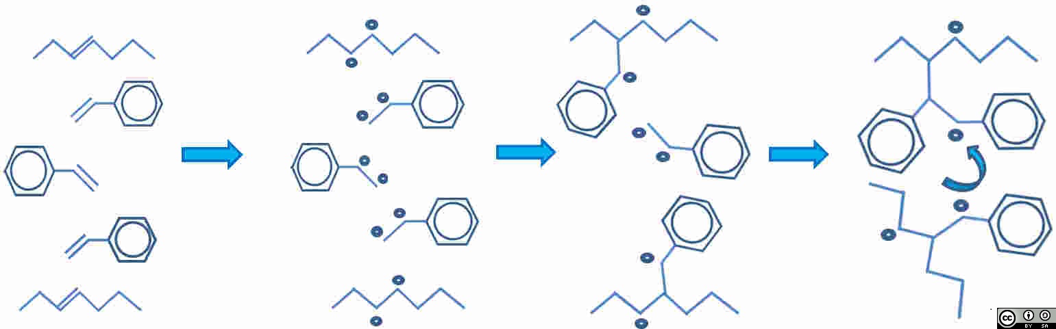
| Unsaturated polyester and styrene both have double bonds. Polyester chain top and bottom, with 3 styrene molecules between. |
A broken bond = two free radicals. Assume all double bonds break. Five double bonds are now ten free radicals |
Free radicals pair-up to make new bonds |
Molecules move closer together and rotate to form cross-link. Net shrinkage of system results. Note two remaining reactive sites. |
![]() Figure 1: The progress of the addition curing reaction in unsaturated polyester.
Figure 1: The progress of the addition curing reaction in unsaturated polyester.
The Figure above (URL) by John Summerscales is licensed under a Creative Commons Attribution-ShareAlike 4.0 International License.
The chemicals chosen for the manufacture of unsaturated polyester resin affect the relative properties. The straight chain (aliphatic) precursors allow local flexibility while conjugated cyclic (aromatic) precursors confer stiffness, strength and thermal stability to the molecule. For a mono-substitued benzene ring (C6H5X, which is phenol when X=OH), further substitution can take place at the first (ortho-), second (meta-) or third (para-/tere-) positions away from the substituted molecule. If a link in the polymer chain passes through the benzene ring, the ortho-position will impose a 60° turn in the steric conformation of the molecule, while meta will change the direction by 120° and para will maintain the line of the molecule (180°). Orthophthalic UPE follows a convoluted path, while (meta- or para-) Isophthalic UPE is a straighter molecule which can pack more densely and hence has higher stiffness, higher strength and improved environmental resistance. Isophthalic polyester resins are the preferred option (vs orthophthalic) for marine applications as they generally have better resistance to water permeation, better chemical/weather resistance, better mechanical strength and strain to failure, and higher heat distortion temperatures. However, the good performance does come at a marginally higher cost. Premium polyester resins often have neopentyl glycol (NPG: 2,2-dimethylpropane-1,3-diol, CAS 126-30-7 ) as the alcohol component to reduce weight loss when heated and confer higher degradation temperatures.
2.1.4 Vinyl ester resin (VE)
Vinyl ester resins have a similar backbone chemistry to epoxide resins but have unsaturated reactive sites positioned at the extreme ends of the molecule. The lower ester group content reduces their susceptibility to hydrolysis. They can be produced by reacting bisphenol A with monocarboxylic acids to produce difunctional molecules with terminal vinyl groups. The crosslinking sites on unsaturated polyester resins are within the backbone of the polymer and the consequent pendant groups at chain ends might reduce Tg, whereas the chain-end crosslinking sites in vinyl ester resins produce a diferent network structure without pendant groups and hence potentially higher glass transition temperatures. They are cured in a similar manner to unsaturated polyesters but the chemical structure produces more resilient/tougher cured polymers.
Methacrylic resins have similar base resins to vinyl esters or unsaturated polyesters, and are cured by addition (opening double bond) reactions. However, they use different reactive diluents, e.g. acetoacetoxyethylmethacrylate ( AAEM, CH3COCH2CO2CH2CH2O2CC(CH3)=CH2, CAS 021282-97-3 ), butyl methacrylate ( CH2=C(CH3)CO2(CH2)3CH3, CAS 97-88-10 ), glycidyl methacrylate ( CH2=C(CH3)CO2CH(O)CH2, CAS 106-91-2 ) or methylmethacrylate ( CH2=C(CH3)CO2CH3, CAS 80-62-6 ) either singly or in mixtures with styrene [201, 202]. The reactive sites are inboard on the polyester molecule, or terminal groups in vinyl ester. The vinyl ester option will have fewer pendant chain ends and hence higher Tg.
2.1.5 Bismaleimide (BMI) resins
The BMI resins are addition polymers characterised by the -(CO)-NX-(CO)- group, i.e. a tertiary amine between two carbonyl groups. When X is an aromatic group, the conjugation of alternating double bonds will spread across the aromatic ring, the amine and both carbonyls to produce a relatively large mechanically and thermally stable planar structural entity. A very wide range of structurally different BMI resins are commercially available for use as adhesives or as the matrix for composites. BMI resins can be cured using standard processing equipment for high-temperature epoxies (i.e. ~180°C) followed by free-standing postcure in an oven at ~250°C to complete the polymerisation and thus achieve even higher properties.
2.2 Thermoplastic polymers
The principal thermoplastic polymers which find use as the matrix for composites are (a) polypropylene, (b) polyamide, (c) polyester and (d) PEEK. For crystalline polymers, the melting point value is normally ~200 (±50)°C above the glass transition temperature ( Tm ≈ Tg + 200°C ).
2.2.1 Poly(propylene) (PP)
Poly(propylene) (PP) is produced by the homopolymerisation of propylene (CH3-CH=CH2). The glass transition occurs below ambient temperature, so the polymer should not be used in highly stressed components as it will creep.
2.2.2 Polyamide (PA)
An amide (-CONH-) is the product of the reaction between a carboxylic acid (-CO2H) and an amine (-NH2) with water as a by-product. Linear polyamide molecules can be produced using either (i) an ω-aminoacid or by ring opening of a cyclic amide (lactam) or (ii) by the reaction of a difunctional acid with a difunctional amine. The former group (i) polyamides are normally denoted PAx, while the two monomer systems (ii) are denoted PAx,y where x is the number of carbon atoms in the amine monomer and y is the number of carbon atoms in the acid monomer (Table 3). Polymers with shorter CH2 sections are more likely to crystallise and to have higher levels of hydrogen bonding betwen molecules, but they are also more likely to be hydrophilic.
2.2.3 Polyesters
An ester (-CO2-) is the product of the reaction between a carboxylic acid (-C02H) and an alcohol (-OH) with water as a by-product. The most common linear polyester molecules are polyethylene terephthalate (PET, terephthalic acid and ethylene glycol) and polybutylene terephtalate (PBT, from ring opening of cyclic butylene terephtalate (CBT)). PET is the only condensation polymer marked for recycling. PBT from CBT is finding increased use in Liquid Composite Moulding (LCM) process, especially Resin Transfer Moulding and Resin Infusion under Flaxible Tooling.
2.2.4 Poly aryl ether ether ketone (PEEK) [254]
The highest performance available from thermoplastic polymers is achieved when a number of aryl (benzene ring) groups are sufficiently close on the backbone of the polymer for electron delocalisation to extend the electron cloud across more than one aryl group. These polymers are known generically as poly aryl ether ketones (PAEK), where ether is an oxygen atom in the backbone conferring molecular flexibility, and where ketone is the double-bonded carbon-oxygen moiety. The principal polymers are poly ether ether ketone (PEEK) and poly ether ketone ketone (PEKK).
| Monomer(s) | Polymer | Density (kg/m3) | Tg (°C) | Tm (°C) | M∞ (%) [253] | E (GPa) | σ′ (MPa) |
| propylene (CH3-CH=CH2) | PP | 900 | -5 | 175 | <0.1 | 1.1-1.3 | 29-34 |
| Polyamides | |||||||
| 1,4-diaminobutane adipic acid HOOC-(CH2)4-COOH |
PA4,6 | 1180 | 295 | <10 (high) | 3 | 80 | |
| caprolactam ↳(CH2)5-CO-NH↲ | PA6 | 1130 | 56 (dry) | 215-221 | <10 (high) | 2.8 | 76 |
| hexamethylene diamine H2N-(CH2)6-NH2
adipic acid HOOC-(CH2)4-COOH | PA6,6 | 1140 | 76 (dry) | 254-264 | <10 (high) | 3 | 80 |
| hexamethylene diamine H2N-(CH2)6-NH2
sebacic acid HOOC-(CH2)8-COOH | PA6,10 | 1090 | 215 | <10 | 2.1 | 55 | |
| laurolactam ↳(CH2)10-CO-NH↲ | PA11 | 1040 | 185 | 190-200 | <10 | 1.4 | 38 |
| dodecanelactam ↳(CH2)11-CO-NH↲ | PA12 | 1020 | 175 | 180-210 | <10 | 1.4 | 45 |
| Polyesters | |||||||
| terephthalic acid and ethylene glycol | PET | 1390 | 67-75°C | 252-265°C | 0.55-2.0 (24h) [251] | 117-173 | |
| cyclic butylene terephtalate | PBT | 1310-1340 | 25-52°C | 225-228°C | <3.0 | 2.34 | 56 |
| Poly aryl ether ketones | |||||||
| poly ether ether ketone [254] | PEEK | 1264-1400 | 143°C | 340°C | 0.5 | 3.6 | 92 |
2.2.5 Bio-polymers
There is increasing interest in bio-based polymers including poly(butylene succinate) (PBS), poly(hydroxyalkanoates) (PHA) and poly(lactic acid) (PLA). These materials may have comparable mechanical properties to synthetic polymers combined with enhanced sustainability (subject to confirmation by an appropriate lifecycle assessment), biodegradability and/or biocompatibility.
3 The reinforcement
3.1 Aramid fibres
Aramid is a contraction of aromatic amide (the final "e" remains in the French name!). The chemical make-up of the synthetic organic fibres alternates the (aromatic) benzene ring (-C6H4-) with the amide (-CONH-) group found in polyamide ("nylon"). The fibres are produced by spinning the rigid-rod-like polymer from a liquid crystal solution in concentrated sulphuric acid. The covalent bonds in the polymer molecule backbone are oriented along the fibre principal axis while the molecules are bound by hydrogen bonds in the radial direction.
Aramid fibres have a unique combination of high modulus, high strength, toughness, thermal stability and chemical resistance. However, as a consequence of the molecular arrangement, the fibres have poor transverse strength and poor compressive properties (compressive strength is generally about 20% of tensile strength. Further, the amide group is hydrophilic, so the fibres absorb moisture. The fibres are degraded by ultraviolet light. Table 4 summarises the principal forms of aramid fibres.
| Trade names | Uses | Density (kg/m3) | Modulus (GPa) | Strength (MPa) | Elongation at break (%) |
| PPPT, PPTA | poly para-phenylene terephthalamide | ||||
| Kevlar® (DuPont) Twaron (Teijin) |
K: rubber tyres, hoses, conveyor belts K29: cables, ropes, ballistics K49: reinforcement fibres ~ |
K: ~ K29: 1440 K49: 1440 T: 1440-1450 |
K: ~ K29: 70.3 K49: 112 T: 60-120 |
K: ~ K29: 2.92 K49: 3.00 T: 2.4-3.6 |
K: ~ K29: 3.6 K49: 2.4 T: 2.2-4.4 |
| PMTA | poly meta-phenylene isophthalamide | ||||
| Nomex® (DuPont) | paper for honeycomb cores | ~ | ~ | ~ | ~ |
| ~ | para aramid copolymer: para-phenylenediamine / diaminodiphenylether / terephthaloyl chloride [304] | ||||
| Technora (Teijin) | 1390 | 74 | 3.4 | 4.5 | |
Special tools and techniques are appropriate for machining aramid composites [305] and these may be more relevant than traditional routes for natural fibre composites. For example [305], the band saw should have a fine tooth blade (550-866 teeth/m) with straight-set or raker-set teeth and operate at high speed to stretch and shear the material. To minimise the production of fuzz and to keep the teeth from snagging fibres run the blade in reverse (teeth pointing upwards) [305]. "As shipped, Kevlar® aramid fiber products do not pose a hazard. Kevlar® staple and pulp contain a small amount of respirable fibers which may become airborne during opening, mixing, carding, or regrinding waste products containing Kevlar®. When mechanically working Kevlar® fiber or materials containing Kevlar® in operations such as cutting, machining, grinding, crushing or sanding, airborne respirable fibers may be formed. Repeated or prolonged inhalation of excessive concentration of respirable fibers may cause permanent lung injury" [306].
3.2 Carbon fibres
Carbon fibres (Table 5) are normally produced from one of three precursor fibres: poly(acrylonitrile) (PAN), pitch or reconstituted cellulose (rayon). The process for PAN will typically involve oxidation under tension at 200-250°C, carbonisation in a non-oxidising atmosphere at 1000°C, then graphitisation in a non-oxidising atmosphere at 2500-3000°C. The resulting fibres have a similar structure to graphite but with a turbostratic layer structure and consequent increased interlayer spacing. The layers become closer to each other, with increased axial elastic modulus, during graphitisation especially at higher temperatures.
| Precursor | Tensile modulus (GPa) | Tensile strength (GPa) | Strain to failure (%) | Density (kg/m3) | Carbon assay (%) |
| Rayon | 41 | 1.1 | 2.5 | 1600 | 99 |
| Pitch | 161 | 1.4 | 0.9 | 1900 | 97 |
| PAN | 231 | 3.4 | 1.4 | 1800 | 94 |
| Pitch | 385 | 1.8 | 0.4 | 2000 | 99 |
| PAN | 392 | 2.5 | 0.6 | 1900 | 100 |
| Pitch (K13D2U) | 931 | 3.7 | 0.4 | 2200 | >99 |
3.3 Glass fibres
Glass fibres are formed by melt spinning specific combinations of oxides dependent on the fibre type (Table 6). E-glass dominates the market.
| Mechanical properties | Composition | ||||||||||||||||||||
| Type | Uses | Density (kg/m3) | Modulus (GPa) | Strength (MPa) | Elongation at break (%) |
SiO2 | Li2O | Na2O | K2O | BeO | MgO | CaO | B2O3 | Al2O3 | TiO2 | Fe2O3 | ZrO2 | CeO2 | PbO | F2 | Reference |
| A-glass | high alkali content for chemical resistance | 2460 | 73 | 3.1 | 3.6 | 72% | ~ | 12.5% | 1.5% | ~ | 0.9% | 9% | 0.5% | 2.5% | ~ | 0.5% | ~ | ~ | ~ | ~ | [301] |
| C-glass | chemical corrosion resistance | 2460 | 74 | 3.1 | ~ | 65% | ~ | 8.5% | ~ | ~ | 3.0% | 14% | 5% | 4% | ~ | 0.5% | ~ | ~ | ~ | ~ | [301] |
| D-glass | low dielectric quartz glass: good transparency to radar | 2140 | 55 | 2.5 | ~ | 73% | ~ | ✔ | ✔ | ~ | ✔ | ✔ | 23% | ✔ | ~ | ~ | ~ | ~ | ~ | ~ | [301] |
| E-glass | electrical insulator. high strength. | 2550 | 71 | 3.4 | 3.37 | 55.2% | ~ | 0.3% | 0.2% | ~ | 3.3% | 18.7% | 7.3% | 14.8% | ~ | 0.3% | ~ | ~ | ~ | 0.3% | [301] |
| L-glass | high lead content for radiation protection | ~ | ~ | ~ | ~ | 62.9% | ~ | ~ | ~ | ~ | 10.3% | ~ | 13.6% | 2.6% | ~ | ~ | 2.1% | ~ | 8.5% | ~ | [307] |
| M-glass | high modulus (rare) | ~ | ~ | ~ | ~ | 53.7% | 3.0% | ~ | ~ | 8.0% | 9.0% | 12.9% | ~ | ~ | 8.0% | 0.5% | 2.0% | 3.0% | ~ | ~ | [308] |
| R-glass | reinforcement grade | 2550 | 86 | 4.4 | 5.2 | 60% | ~ | ~ | ~ | ~ | 6% | 9% | ~ | 25% | ~ | ~ | ~ | ~ | ~ | ~ | [301] |
| S-glass | high strength, high modulus and high temperature resistance grade: ballistics | 2500 | 85 | 4.58 | 4.6 | 65% | ~ | ~ | ~ | ~ | 10% | ~ | ~ | 25% | 1.4% | ~ | ~ | ~ | ~ | ~ | [301] |
3.4 Other reinforcement fibres
A variety of other fibres have been proposed as the reinforcements for composites, including Ultra-High Molecular Weight Poly Ethylene (UHMWPE, e.g. Dyneema and Spectra), the polybenz[x]azole (PBX) rigid-rod polymers (e.g. PBI: poly(benzimidazole), PBO: poly(benzoxazole) or PBT: poly(benzthiazole where [x] is nitrogen, oxygen or sulphur respectively).
Sustainability issues have revived interest in natural fibres which may be animal (feather, hair, silk or wool), mineral (asbestos or basalt) or vegetable. Plant fibres may be extracted from the stem (bast), leaf, fruit/seed, root, grass or wood. The most extensively explored bast fibres are flax, hemp or nettle from temperate climates or jute, kenaf or ramie from tropical climates.
4 The fibre-matrix interface
The rules-of-mixture for the estimation of the mechanical properties of a composite assume that the fibre-to-matrix interface is completely bonded. Interfacial bonding has been reviewed by several authors [401-408]. The reinforcement fibres are normally supplied with a surface coating ("size" or "sizing") which promotes good bonding between the two adherends. Coupling agents are often small molecules where the silane end bonds to the fibres and the other end is specific to the matrix system. For example, vinylsilanes are used with unsaturated polyester or vinylester resins, while epoxysilanes are used with epoxy resins. The chemical activity of these two systems is very different. A quick rule-of-thumb would be that glass fibres are sized for vinyl curing systems (unsaturated polyester or vinyl ester) and "advanced" (e.g. aramid or carbon) fibres are sized for use with epoxy. If unsure what system is in use, it is appropriate to check with the supplier before committing to manufacture safety critical structures.
5 Reinforcement forms
The reinforcement fibres can be arranged in a variety of different ways. The configuration of the reinforcement sets ranges for both the achievable fibre volume fraction and the reinforcing efficiency (Table 7).
| Configuration | Volume fraction range | Fibre orientation distribution factor |
| Random | 10-30% | 0.375 (all directions in plane) |
| 2-D fabric | 30-60% | 0.5 (ignoring out-of-plane crimp) |
| 3-D woven | ||
| Unidirectional | 50-80% | 1.0 |
Such et al [501] present an overview of the history of aligned discontinuous fibre composites. They focus on the process and application of highly aligned advanced composites with properties that approach those of continuous fibre composites. Aligned discontinuous fibre composites may be created by aligning short fibres or introducing discontinuities into aligned fibres in order to produce components with complex topologies.
There is increasing interest in using very thin layers within laminates. In 1984, Richards et al [502] described an aircomb technique for spreading reinforcement tows. North TPT (Thin Ply Technology) [503-504] now produce lightweight unidirectional carbon fibre/epoxy prepreg tapes as light as 15 gm-2 (gsm). Borg [505], Ohlsson [506] and Gardiner [506a] have recently reviewed the current status of spread tow reinforcements.
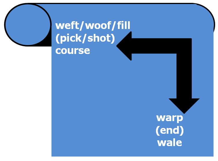
Planar reinforcements (fabrics) are produced by textile processes including weaving, knitting and stitching. The terminology for the yarns in a cloth are given in Table 8. Fabrics are characterised by the mode of construction (see beow) and their areal weight (measured in grams per square metre: gm-2 or gsm). Continuous fibres for the reinforcement of advanced composites are normally supplied to textile processes on spools. The spools are mounted onto a creel frame which controls the unwinding, tensioning and guiding of the fibres, yarns or tapes. Glass fibres may be pulled from the inside of the spool when there is no precise requirement for tension control. Tension controllers [507] (known as tensioners or dancers) may use a servo-controlled torque motor, a pneumatic cylinder, a magnetic particle brake or a magnetic particle clutch.
 |
|
5.1 Woven fabrics
Woven fabrics normally consist of two sets of interlaced orthogonal fibres produced on a loom. For a balanced fabric (equal numbers of tows/metre with the same linear density in each direction), the in-plane fibre orientation distribution is 0.5 when loaded on one set of fibres or 0.25 when loaded on the bias (stress at ±45° to the fibres). The interlacing causes undulation of the fibres out-of-plane. Crimp is defined [508] as "the waviness of a fibre" and is normally expressed numerically as either "the number of waves or crimps per unit length" or "the difference in distance between points on the fibre as it lies in a crimped condition and the same two points when the fibre is straightened under suitable tension". The fibre orientation distribution factor will be reduced dependent on the degree of out-of-plane crimp.
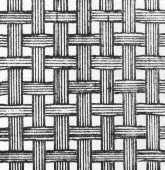
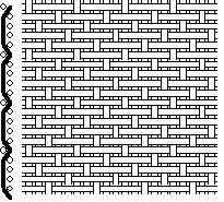
When used for the reinforcement of composites, textile fabrics are normally woven in one of three styles: plain, twill or satin (Figure 2).
| plain weave: | twill weave [NRLP]: | 5-harness satin weave [NRLP]: | ||
 |
 |
 |
Whilst the vast majority of woven reinforcements are in the form of two-dimensional planar fabrics with orthogonal fibres, it is also possible to produce triaxial weaves where the fibres are at 0° and ±60°.
5.2 Stitched or knitted fabrics
Stitched fabrics are bound together by a lightweight fibre loop sewn or knitted around the reinforcement tow. The fabrics may be just a single unidirectional layer, or multiple layers. A multi-layer fabric may be biaxial (0°/90° or ±45° cross-plied for two layers, or 0°/90°/0° for three layer with two parallel layers) or multi-axial (e.g. triaxial as 0°/+45°/-45° or quadriaxial as 0°/+45°/-45°/90°). The reinforcement tow remains aligned in the plane without crimp, so these reinforcements are commonly referred to as non-crimp fabrics (NCF). NCF have the potential for a higher fibre orientation distribution factor than for a woven fabric and each unidirectional layer can pack with the possibility of higher fibre volume fractions than is possible in woven fabrics. It is important that full consideration is given to selection of the stitching fibre as poor resin penetration or a poor bond to this thread could be a precursor to laminate failure.
Modern knitting machines permit the insertion of unidirectional reinforcement tows in a "matrix" of knitted loops. Where fibres are inserted across the width of the machine, a weft-insertion warp knit fabric is produced but the reinforcement length is limited to the roll width. The alternative is warp-insetion weft knit (WIWK) fabric where the reinforcement length is only limited by the size of the roll.
5.4 Braids
Braiding is defined by the Textile Institute [508] as "the process of interlacing three or more threads in such a way that they cross one another and are laid in a diagonal formation, and is the subject of a book by Kyosev [509]. Flat tubular or solid constructions may be formed in this way". A typical braiding machine operates using a "maypole" action whereby half of the yarn carriers rotate on a clockwise path whilst weaving in and out of the remaining 50% of the yarn carriers which are following a counter-clockwise path. In the tubular braided reinforcement, each fibre follows a helical path around the principal axis of the braid. Ayranci and Carey [510] have reviewed the use of 2-D braided composites for stiffness critical applications. The modelling of the mechanical properties of textile braids has been considered by a number of authors [e.g. 511-517].
5.5 Three-dimensional woven fabrics
There is increasing interest in 3-D textile reinforcements [518-522] which find application primarily as preforms for Liquid Composite Moulding (LCM) processes, including Resin Transfer Moulding (RTM) and Resin Infusion under Flexible Tooling (RIFT). Bogdanovich and Mohamed [522] make a clear distinction between 3D interlock weave (either layer-by-layer with the interlock only running though a limited number of layers, or angle-interlock with binder fibres running through the full fabric thickness) and 3D orthogonal non-crimp weave (with binder fibres running at 90° to the two other sets of tows).
5.6 Preforms
A preform is an assembly of reinforcement which is a close reproduction of the component shape. Preforms are normally prepared outside the mould tool and loaded as a single entity to permit reduced overall cycle times. A preform must normally have sufficient rigidity and integrity to permit transfer into the tool without losing net-shape.
5.7 Pre-impregnated reinforcements (prepregs) [523]
For vacuum-bagging (and autoclave cure) processes, control of the resin mixing and quality can be transferred to the material supplier by having the reinforcement pre-impregnated with the resin system. Systems with an unsturated polyester resin matrix, are normally supplied just-in-time (JIT) and are known as "moulding componds". For higher performance structures, epoxy prepregs are generaly classified according to their cure temperature (Table 9).
| System | Normal cure temperature |
| low temperature | 60±30°C |
| medium temperature | 120±30°C |
| high temperature | 180±30°C |
6 Sandwich structures
Sandwich structures consist of stiff, strong skins either side of a lightweight core. This configuration moves the reinforcement materials away from the neutral axis of a beam or plate conferring higher stiffness without a significant increase in weight. A sandwich structure can be considered as an I-beam where the skins replace the flanges and the core replaces the web. The selection of skin materials follows the approach described above for monolithic composites. The core may be a natural material, polymeric foam, corrugated structure or honeycomb (Table 10).
| System | Density (kg/m3) | Elastic modulus (MPa) | Shear modulus (MPa) | Compression strength (MPa) | Shear strength (MPa) | Elongation at break (%) | Thermal conductivity (mW/m.K) | Thermal expansion (μm/m.K) | Reference |
| end-grain balsa | 130 | 3000 | 230 | 7 | 1.2 | 100 | 6.5 | [601] | |
| compressed cork | 150 | 20 | 10 | 1 | 15 | 40 | 200 | [601] | |
| polyurethane (PUF) | 60 | 20 | 4.1 | 0.42 | 0.41 | 30 | 30 | [602] | |
| polyvinyl chloride (linear PVC) | 50-80 | 37-56 | 15-21 | 0.4-0.9 | 0.5-1.2 | 80 | 33-35 | [602] | |
| polyvinyl chloride (cross-linked PVC) | 40-200 | 26-223 | 12-77 | 0.5-4.6 | 0.4-3.5 | 10-31 | 29-42 | [602] | |
| styrene-acrylonitrile (SAN) | 200-400 | 155-350 | 60-240 | 4-13 | 3-8 | 6-7 | 48-55 | [602] | |
| polymethacrylimide (PMI) | 32-110 | 35-180 | 13-70 | 0.80-3.6 | 0.8-2.4 | 3.0-7 | 29-31 | 3-37 | [603] |
| Nomex® honeycomb | 29-48 | 60-140 | 17-40 | 0.9-2.4 | 0.35-1.2 | [604] |
7 Acknowledgements
The author is grateful to Aitor Hernandez Michelena (doctoral student) for drawing attention to references which might otherwise have not been incorporated in the text. Indicative data for materials may not fully represent the range of possibilities. Trade Marks and similar designations are included for traceability: the author does not intend to endorse a specific product by any such inclusion.
8 References